
In a blog I posted last year, I described how I developed a series of AppleScripts to control Adobe Photoshop to crop, then increase the canvas size, then draw crop marks on a series of image parts to make a very large panoramic image on 10 sheets of photographic aluminum. That panorama is now on permanent display in the University Union at California Polytechnic State University, San Luis Obispo, California.
In my most recent blog I described how I prepared 63 monochrome images taken by the Opportunity Rover on the surface of Mars to make a large full color panoramic image for the Baker Center, also on the Cal Poly campus.
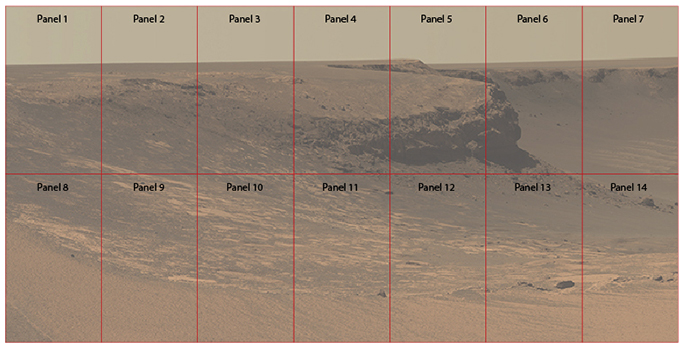
The is the pattern for cutting the large panoramic image into its 14 printed panels. The aluminum material is available in sizes up to 48 x 96 inches. This image, when finished, was 22 feet wide and about 12 feet tall.
The large panoramic image was finished, and it looked great, but to print it, I had to divide it into 14 separate panels (two rows of seven) to make the photo ready for attachment to the wall at school. This required AppleScript, again, and Photoshop, again. But, this time I had two dimensions to worry about – two rows of photos that had to be printed and mounted with absolutely no error that would cause them not to match on any of their two or three touching sides.
This is quite difficult, because first I had to make the files ready, then have them printed onto paper (they are printed as mirror images), then transferred to the aluminum sheets in a dye-sublimation printing process. They then had to be cut on a mechanical metal-cutting shear, and ultimately assembled on the wall. Perfectly.
Any error at all would be visible as a gap between either the sides or the tops and bottoms of adjacent panels. Or both.
My effort began with an AppleScript that crops the large master image into one of the 14 panels. The cropping included one-half inch of bleed, and overlap, to be cut off on the metal shear. The left two panels had a one-half inch white space added while the right two panels had that gap added on the right. The middle panels overlap on both sides.
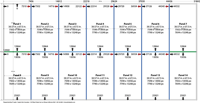
This is the road map I generated in Adobe Illustrator to guide me in making my AppleScripts. Precision to the pixel is necessary for a project like this, and the map made the process easier.
The top seven panels overlap at the bottom by one-half inch, while the bottom seven overlap on the tops. White was added to the opposite edges.
My script is run successively on the same image because of the overlaps. My technique was to write all the AppleScript/Photoshop script instructions in order, then comment them out (making each line start with a double-hyphen). Then I would remove the comment mark, run the script, save the result as a separate cropped (with overlaps) file, then use the History palette to return to the uncropped original, and run the next line in the script.
This is one line of that script, the line that crops the upper-left panel from the original large file:
crop current document bounds {0,0, 7502, 13056} angle 0 width 7502 height 13056 -- Crops Panel 1
This crops from position 0, 0 (absolute upper-left) to 7,502 pixels to the right, and 13,056 pixels down. This includes the one-half inch overlap on the right and bottom edges. The next line of my script is very similar, except that it starts 192 pixels to the left of the right extreme of the previous line (one-inch):
crop current document bounds {7310, 0, 14908, 13056} angle 0 width 7598 height 13056 -- Crops Panel 2
This manually executed script resulted in the 14 separate panel files being ready for the next step in the process. For that I wrote another AppleScript to instruct Photoshop to add canvas space and crop marks to the four corners of the panels. These crop marks must be absolutely accurate, which is why I use the script to make them. I have pixel-precision with these scripts, something that I do’t have if I do it by hand (I would never attempt this). Even a one-pixel error would result in a skew or a gap in the shearing step.
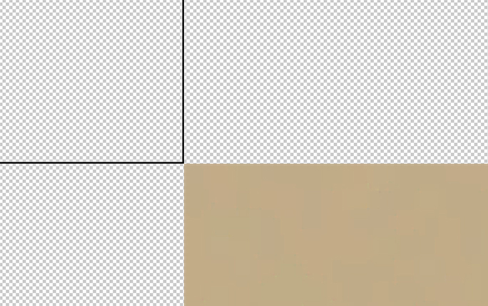
This is an extreme close-up of an upper-left crop marks set. These marks are outside the image area of each panel, touching exactly at the corner. The AppleScript instructs Adobe Photoshop to draw the marks at the four corners of the images.
My final script put a text label at the bottom-center of each panel. These Mars photo segments tend to look alike, and it was important to keep them in the right order.
The files were sent to a firm that specializes in printing on aluminum sheets using the dye-sublimation process. They use two Epson wide-format ink-jet printers to make the paper images that carry the dye-sub ink, and they have a custom-built press for making the transfers to the aluminum material. The catch is that they don’t have a metal shear large enough to cut these panels, so that part of the job came to our town where “Stainless Steve” Rinnell’s metal shop came into the story. I called on Steve’s expert help and his massive metal-cutting shear on two earlier projects.
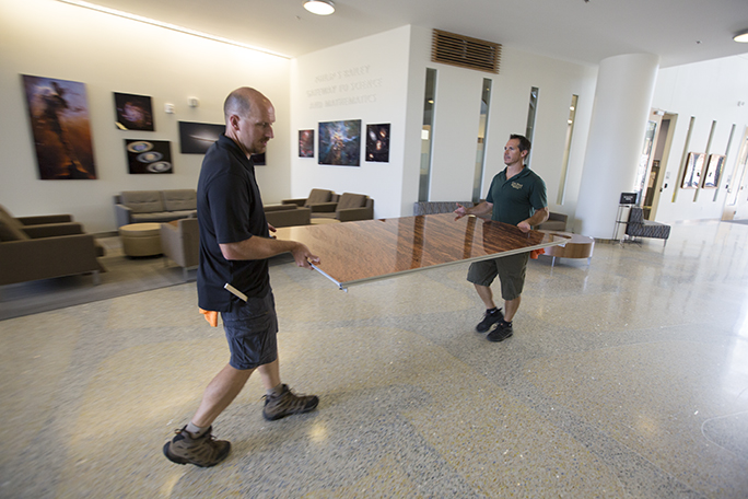
Doug and Rob Brewster, brothers and technician-engineers for the College of Science and Mathematics at Cal Poly, carry one of the Mars photo panels to its destination in the Baker Science Center.
Two skillful technicians from the College of Science and Math at Cal Poly enter the story here. Meet Doug and Rob Brewster, two of the smartest, kindest and most competent mechanical geniuses I have ever had the pleasure to know. They supervised and participated in the shearing process (I wasn’t there this time), and they did the job perfectly (it is the one precarious step in the process that is done by eye).
Rob devised a clever device and method for positioning the Mars panels that would ensure that they would go up in perfect position. Rob used the shop at Cal Poly to make aluminum blocks with tiny adjustment pads that would allow each panel to be hung on a wall-mounted rail system, then adjusted until the panels fit perfectly.
The rails were mounted on the wall in the Baker Center by the University’s Facilities technicians, a requirement for anything that is mounted permanently on the walls of campus buildings. After they did their work, Rob checked the flatness of the grid to discover that the wall behind it wasn’t perfectly flat, so he shimmed the rail mountings using a laser beam until the mounting rails were absolutely flat.

Doug and Rob on a scissor-lift put the tenth panel in place on a grid of aluminum rails attached to the walls of the Baker Center at Cal Poly.
After that step, Rob and Doug made a set of four 3-D printed plastic register blocks that were mounted on the corners of each panel’s support rails. These blocks allowed the men to position the aluminum panels perfectly on their frames prior to being mounted on the wall. These impressive points of control gave Rob abd Doug the confidence that the assembly of the panels would go perfectly. We had no room for error at any point, and the mounting of the photo panels was the ultimate step in seeing this project to completion.
I watched them as a few of the panels were attached, and I returned a few times to check on progress. But, my role in the project was strictly supervisory (observational) at this point. The project was now in the hands of the pros!
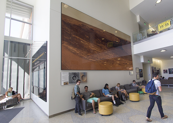
This is the final Mars panoramic image on the wall in the Baker Center. At the lower-left is a legend of the photo, showing the position of the rover when the images were made, and describing the Mars exploration efforts of NASA, JPL, and the other institutions involved in the project. Photo by Eric Johnson
I am proud to say that the collaboration worked perfectly. The panels were up, and there were no errors in the cutting or the mounting. The photo is stunning! And, looking at it now, all I see is the Cape Verde peninsula on the side of Duck Bay in the Victoria Crater on the surface of Mars. It is very exciting to see this project completed.
Others working on the project included Michele Murfin-Fanning, the Interior Designer for the building, Dr. Phil Bailey, Dean of the College of Science and Mathematics, Professors Derek Gragson and John Keller, and Dave Clendenen, the talented photographer who helped to document the project’s construction.
Brian, that is a gorgeous project. It is so impressive and suits the space perfectly.
I am in such strong agreement to your comment here “…the smartest, kindest and most competent mechanical geniuses I have ever had the pleasure to know.” It is such great thing to watch people do a job well.
Wow! Fantastic job, Brian, and beautiful. Thanks for the blog description of the process. I still can’t believe that an eye-sighted shear cut can be that consistently accurate. There are truly some talented people around.
Thanks for this additional donation to the beauty of Cal Poly’s campus.