

My friend Bryn and I own a CNC router. We have had it for years, and it has undergone a couple of upgrades. It started life as a CNC Machine with a DeWalt router motor mounted on it, providing adequate, but not impressive cutting speed and depth. We each burned up a DeWalt router before we decided to upgrade to a more powerful spindle motor. (No offense meant to the DeWalt router – it’s a fine power tool, but it is not up to the task of CNC machining.) We updated with a 220V spindle motor that is much more powerful, and which provides more power for cutting.
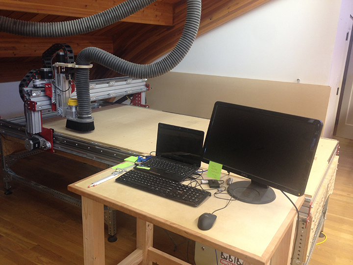
The machine was built from parts available from AVID CNC, formerly known as CNC Parts. Ours is just over 4 x 8 feet in size. We have it hooked up to our shop dust collection system, and we have a compressed air line attached to the spindle to deliver an air blast to the cutting tool when needed.
When we first got the machine, I invested in a laser positioning device (from SDA Manufacturing, LLC) that can be mounted in the spindle, allowing us to make extraordinarily accurate positioning and measurement settings. That laser has served us well. To use it, I mount it in a 1/4-inch collet on the spindle, turn it on, and then move the spindle to the position I want to measure or find, and set the machine accordingly. When finished, I take it out and replace it with the cutting tool I intend to use.
That’s not difficult, but it’s a bit tedious. I have wanted a fixed laser positioning tool on the spindle for a long time, making the laser a permanent part of the machine. I want to be able to turn on the laser positioning tool, move the machine, and then get to work without having to change the laser out and the cutter in.

There was no commercial laser device available for our machine so I designed one myself. I determined that I couldn’t drill into the spindle motor to mount a laser there, but I thought that I could make a bracket that attaches to the spindle motor base that would hold a laser in position.
I started looking for small battery powered lasers appropriate to the task, and found one that would work. It’s a gun-sight laser, designed to be attached to the barrel of a pistol or rifle. Moderately powerful, it looked like it would work nicely for the application at hand. I ordered it from Amazon. I also discovered that when it comes to rifle accessories, there are several that attach using a more-of-less standard attachment rail. I bought 10mm of that rail also. The laser is designed to clamp to that rail.
(SDA Manufacturing makes a version of their laser that is possibly better than mine. It comes with a mounting bracket, has microscopic adjustments for alignment, and a permanent power supply instead of batteries.)

My plan was to attach the rail to my bracket, attach the laser to the rail, and have a fixed positioning laser on the machine. Simple!
The laser arrived and it was nearly perfect, but it was much too powerful and the beam too big and bright for the application. Bryn has a Glowforge laser cutting machine, so I asked him to laser-cut some very small apertures in black acrylic material, and I experimented with those as fixed apertures on the gun-sight laser. The smallest one – 0.24 mm – worked perfectly. It both attenuated and limited the laser beam to one that would work in a distance measured in inches. I glued the aperture to the front of the laser body with Superglue.
I designed a bracket that would go around the motor base without drilling any holes. It consists of a horseshoe piece with a faceplate that holds the laser vertically on the side of the motor. It is possible to align this laser with the X-axis of the cutter (left-right), which makes operation much simpler.
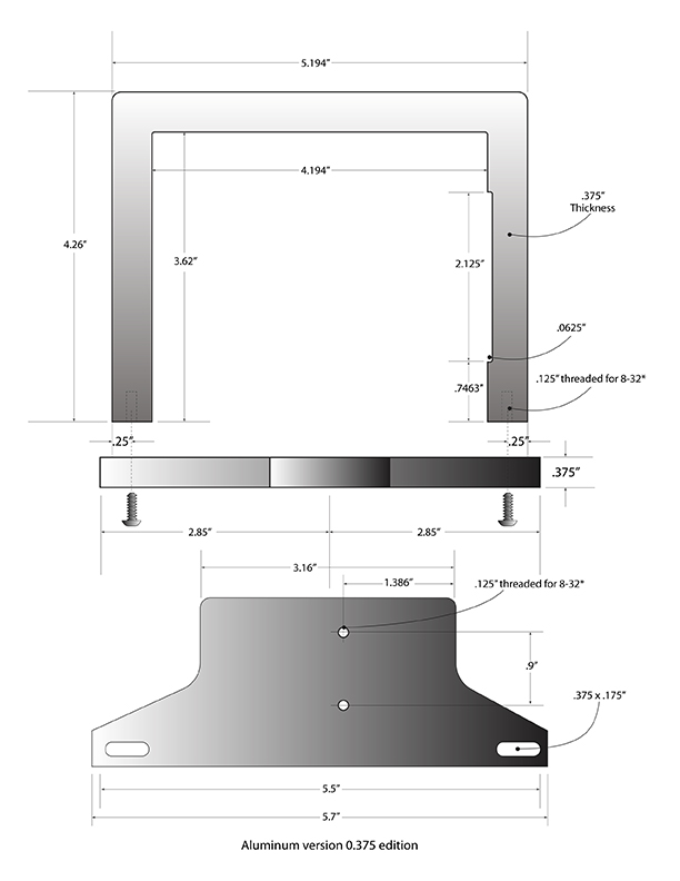
I drew my bracket in Adobe Illustrator – my go-to application for these projects – and came up with the two-part bracket I needed. My plan was to cut it out of aluminum plate, but for prototyping I decided to make the first edition out of wood. I have a stock of Ipé wood in various sizes. This is a Brazilian “Walnut” of the genus Handroanthus. I have years of experience with this wood, and I have a love/hate relationship with it. I love it because it’s beautiful and very hard. I hate it because it dulls every blade that touches it.
For this project it would be perfect, because it is so hard. It machines reasonably reasonably easily, and can be cut with standard milling tools. It is quite brittle, but exceedingly strong.
I planed a board to 0.375 in. thickness and mounted it on the base of the CNC machine. From there I did my machining to make the two pieces for my laser bracket. Both parts have threaded holes for the final assembly, and I drilled the appropriate tap hole sizes for those holes into the wood. Making threads in Ipé is easy. Once the tap holes were drilled, I dripped Superglue into the holes and allowed it to harden. Then I ran my tap into the hole and cut the threads. This worked very well, and the threaded holes work nicely.
I mounted the bracket onto the spindle motor and tightened it at the base of the motor. From here it was stable. Then I mounted the gun-stock bracket to the wooden bracket and tightened it in place.
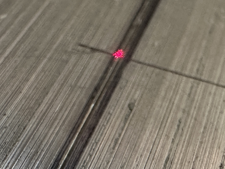
I mounted my new laser onto the bracket, then began to align it to the spindle. I drew a black felt pen line on an aluminum plate, then, using an awl, I scratched a fine line down the center of that black line (along the vertical Y-axis). I put the positioning laser into the collet, and aimed that on the scratched line by moving the gantry left and right (X-axis) until the reflection of the positioning laser was perfect. I moved the aluminum plate carefully until the laser reflected the same along its vertical (Y) axis. Then I moved the positioning laser to the upper end of the scribed line.
Then I turned on my newly mounted laser; its beam reflected off the aluminum plate, but it was about 1/8 inch away from the line. That laser has two hex screws for positioning, so I inserted a hex wrench into one and adjusted the beam slightly toward the line. Then I switched to the other set screw and adjusted it further. Within a few minutes I had both lasers reflecting perfectly along the X-axis line.
The next step was calculating the Y-offset. With the two lasers aligned on the X-axis, I scribed a cross-line where the spindle-mounted laser beam struck the X-axis line. Then I zeroed the Y-axis in software.
Noting the Y-axis position, I moved the spindle along the Y-axis until the new fixed laser reached the cross-scribed line and took note of the new position. Subtracting one from the other I determined the offset to be 3.0453 in. That is my Y-offset for using the new fixed laser beam for positioning.
My method for using the new fixed positioning laser is to point it where I want it, then go into the second menu of Mach 3 (where I can enter G-code commands) and issue a G0 Y3.0453 command, which moves the spindle the distance of the Y-offset. Then I switch back to the main Mach 3 menu and reset the Y to zero again.
Over a period of days, I was successful in using the new fixed laser to position the spindle. At one point, though, I was realized that it was not positioned correctly. It was pointing to the left of the edge of a board when it should have been right on the edge of that board. I took out my scribed aluminum plate again and re-ran the alignment process. I think that the positioning laser’s set screws vibrated off position (I’ll come back to this).
That error notwithstanding, I decided to make an aluminum version of the bracket and make it a permanent part of the system.
For part two of this story, please click here.