
This is Part 2 of my story about restoring an antique Hammond Glider “TrimOsaw” for the Shakespeare Press Museum at Cal Poly. To read the first part, click here.
I got to the point of removing the aluminum nameplate from the front of the saw. This was delicate work. I ground the heads off of the four rivets that held that plate on the machine with a Dremel mini-grinder.

Drilling-out the holes of those rivets proved nearly impossible. I drilled and I drilled and I got nowhere. After consulting with a machinist friend, I invested in two 1/8 in. carbide drills at $30 each. These, he assured me, would drill through anything. The rivets used by Hammond were made of stainless steel which cannot be drilled easily with conventional twist drills. The man who sold me the carbide drills promised me that I needed two because I would break one. He was right. I made three flawless holes with one drill, and then broke a drill on the fourth. So, each hole cost about $15 to drill.
Removing the several coats of paint was a dirty job, most of it done with an industrial angle grinder. The process left the shop filled with acrid smoke and a cloud of particulate. Those N95 masks have purposes other than virus protection! Once I had the paint removed, I rolled the machine into the paint booth and sprayed it with the special green paint I had chosen.
After two coats of paint, and a day for drying, I started to reassemble the machine. I installed the motor, replaced all the conduits and then wired the machine. Because I am obsessive about these projects, I had drawn detailed wiring diagrams, and acquired the necessary parts to do the job professionally, with everything compliant with current electrical codes.
Because table saws are inherently dangerous, I installed a magnetic motor switch on the saw. This ensures that the saw will not restart after a power failure. I also installed a massive master power switch with a lock-out, so that the machine can be locked off to prevent unauthorized or untrained people from operating it.
I used stranded copper wire throughout, as required for any wiring in flexible conduit. This makes it possible for the motor to move (it moves when the depth of cut is changed) without bending solid wires. Again, this is a code requirement as well as a practical idea.
I completely rebuilt the micrometer miter gauge, cleaning out dirt and chips from its internal workings. It is made of chrome-plated steel mixed with aluminum parts, so it had not rusted over the decades in storage. It is gleaming now. The blade guard is cast aluminum, and it showed a lot of wear. I wire-brushed it, then polished it on a buffing wheel, resulting in a concours d’elegance appearance.
Completing the work, I wire-brushed the work lamp, which is a gooseneck of chrome-plated steel. The small amount of rust came off easily, restoring it to like-new appearance. That work lamp does not have a ground wire, so I checked the code, and discovered that work lights often do not require a separate ground wire. When connected to the body of the machine, the steel itself provides an adequate ground. That was lucky because I could not have fished a new ground wire through that gooseneck.
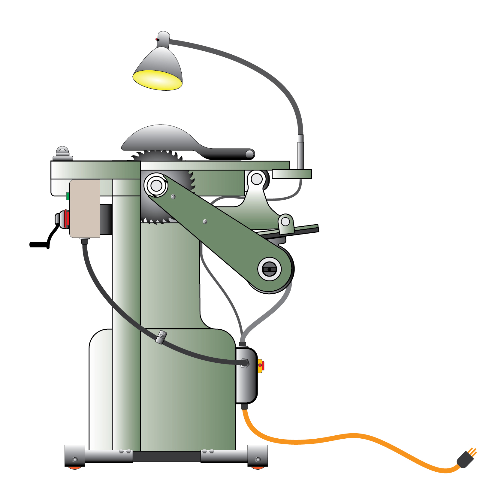
The last part on the saw was the belt guard. It had one when it was manufactured, but somewhere that had been removed and discarded. I found a copy of the original instruction manual online, showing a photo of the machine, but not from the side with the belt guard. There are two steel studs on the machine that obviously held a guard in place, so I designed one in Adobe Illustrator then figured out how to make it.
I began by making one on my CNC machine using a Sharpie marker and running the machine to draw with that marker on a sheet of corrugated board. Then I cut that out and positioned it on the machine. I made several drafts of the guard that way, until I felt I was ready to make the final guard out of aluminum plate.
The flat plate was the easy part, while the curved sheet metal part was more complex. It had to envelope the belts without touching them at any point in the travel of the motor and pulleys. The second step was to cut the belt plate out of a material called Alupanel. This is a material made of two thin layers of aluminum sandwiched with a layer of plastic between them. It is light, moderately strong, and it can be bent, rolled and machined like aluminum, but at a fraction of the cost and time needed to do the work in solid metal. I bolted the first part on to the machine and tested it through the range of motor movement. At the small end, it hit the machine’s lift mechanism, so I modified its design to prevent that. In the end, I had made three versions of the plate. The third was successful.
For the sheet metal I needed strength and bendability which I could not get from Alupanel. I sought the help of my machinist/welder friend Hank Van Gaale. He suggested sheet steel, and water-jet cutting. I had been prepared to cut sheet metal with a pair of shears, but I was excited to see and use water-jet.
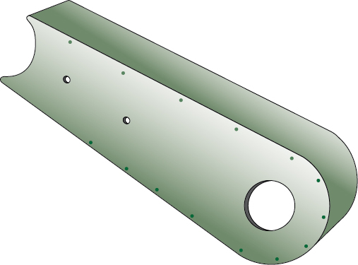
My belt guard is comprised of the Alupanel front plate, and then it has the sheet steel formed into a two-inch protector that covers the V-belts to keep fingers out. I cut a 1/16 in. groove in the front panel, expecting the sheet steel to be inserted into that groove. Along the edge of the same sheet steel I put fold-out tabs with small holes for rivets to be placed, holding the guard at 90 degrees to the front plate.
I designed the sheet steel part in Adobe Illustrator, including three folded hems, all of the rivet tabs, and the parts that sit inside the groove. I submitted the drawing, formatted in AutoCAD dxf format to the water-jet company. There, it was opened in their machining program, positioned, and prepared for cutting.

The water-jet is a CNC machine with a .014 in. diamond orifice that supplies water with garnet abrasive at a pressure of 50,000 psi. This jet of abrasive liquid cuts through the steel (or nearly any other substance) as if it’s not there. Cutting my piece took less than three minutes.
To view a short video clip of the water-jet machine cutting this part, click here.
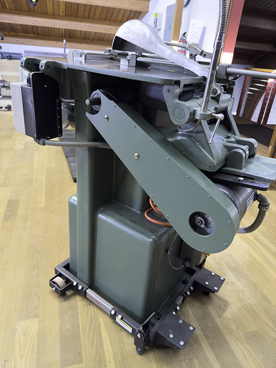
We used 18 gauge steel (0.04 in.), so folding the hems was easy using a bending brake, and rolling the curve was also easy, using a rolling machine. The last part was folding the tabs over 90 degrees with a pair of pliers, then affixing the steel on my front plate, drilling holes and attaching the tabs with pop-rivets.
In the end, the guard is quite handsome. Perhaps it’s too fancy, but I didn’t have a plan for it when I started, and water-jet cut steel worked perfectly. The guard is now mounted on the machine, and the project is finished. It’s now back in the museum at the university. There, I hope, it gets some use cutting slugs made on the Linotype machine.
An addendum: I awoke from a dream night-before-last. I was dreaming that the saw project was not finished. Where there was once a rolling trimmings box under the saw there is nothing now. Somewhere that cart was lost. I had left the space open. But, when used, the trimmings from the saw fall down through the machine and onto the floor. That is unacceptable. So, today I remedied that by building a drawer that slides into the opening under the saw. It slides out over the rolling base frame, and allows for the removal of the trimmings from time to time. Now the project can really be declared finished!
Addendum, February 12, 2023
After I delivered the saw to the museum, I ran it to demonstrate it to the student curators, and it didn’t run very well. I made note of the problem, which appeared to be V-belt slippage, then I disassembled the back-end of the saw and took the motor mount plate off the machine. Back to the shop, I put it on the CNC machine and cut four slotted holes in the plate where it mounts to the saw body.
These slotted holes will allow for the motor to be moved about .5 inch front-back to add or reduce tension on the V-belts. I think this will solve the problem of power getting to the blade of the saw.
While I had it apart, I installed a new start capacitor on the motor (it didn’t need one, but who knows?) and I changed the motor wiring from a (not very) flexible oil-tight conduit to a rubber insulated cord with strain reliefs on both ends. This makes the motor much more flexible, and will allow it to hang on its bracket, providing better V-belt tension. I think these two modifications will make the saw work better. And then my project will really be done!