

This is part 2 of my article about building a fixed positioning laser on the CNC machine. To read the first part, click here.
I had decided to make the final fixed laser with a bracket made of aluminum.
In the weeks in between, I practiced cutting aluminum with various cutters, various speeds, and various feed-rates. This was not my first attempt to cut aluminum; I have done it successfully – and unsuccessfully – before, and I felt that I could make these parts perfectly with my experience in aluminum cutting.
I bought a plate of 3/8 in. aluminum and mounted that on the spoilboard. Then I transferred my drawings into V-Carve (the software that I use to make the G-Code instructions for cutting). V-Carve is capable of importing vectors from Adobe Illustrator (and perhaps other applications) and making them available to its drawing environment.
In Illustrator, I had made a roughing cut line 0.005 in. away from the final dimensions, and another on the final dimension lines. This is easy in Illustrator with its Offset Path function.
I watched several YouTube videos on how to cut aluminum on a CNC machine, and I read as much as I could find on the subject. I decided to use a single-flute 1/4 in. end mill and turn it at 10,000 rpm. I chose to run the cutting tool at only 10 inches per minute. This was a compromise between getting the “chip load” right, and not driving the mill so fast that it would burden the cutter and the machine or get too hot and clog up with aluminum chips.
I experimented on a scrap first, and was very pleased with the results. I decided to make the final pieces (though the pessimist in me had ordered enough aluminum to do it twice).
Then, armed with a can of WD40 to be used as a spray lubricant and coolant, I set up the machine and started cutting. I was taking very small vertical steps into the aluminum (0.05 in.), again not wanting to put too much load on the cutter. It was working quite well, so I continued with the process.
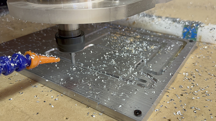
It took almost an hour to make the two parts, but the result was perfect. My surfaces are smooth, and the parts fit together nicely.
I then used my vertical positioning jig to drill the two tap holes into the ends of the horseshoe part, and used “pecking” to drill the holes without breaking the small end mill cutter (0.125 in.). The vertical jig was created by cutting a hole through the spoil board on the machine, and adding T-slot grooves on a bracket that runs vertically under the table surface. This allows me to clamp work on-edge and machine the end of that work. I locked the horse shoe part in the jig and did the drilling with the precision I needed for this step.
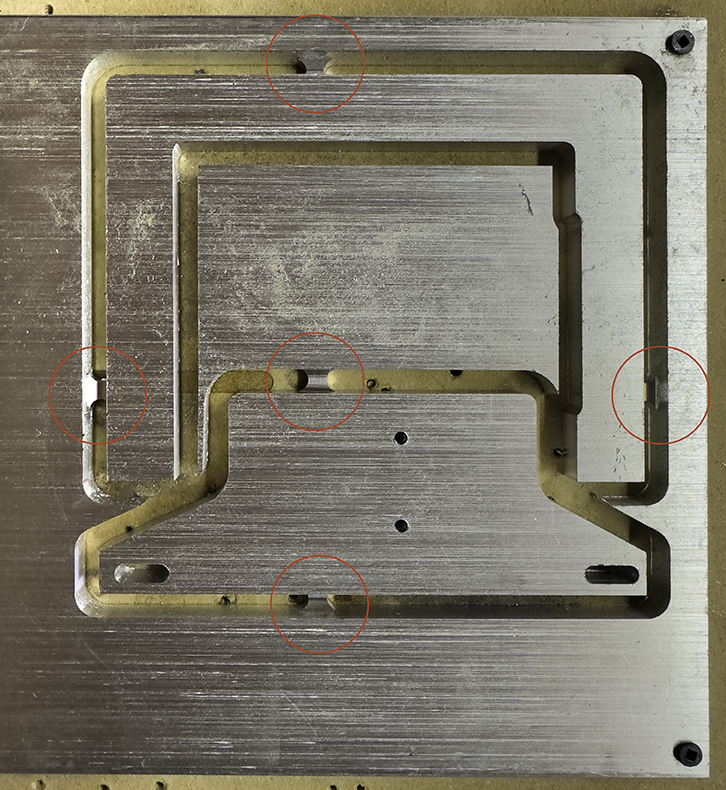
My biggest mistake in milling the aluminum was using tabs to hold the aluminum to the plate while it was being machined. Tabs are small sections along the edge of work that are left uncut to hold the work to the larger material. These tabs ended up being too big, and it required quite a lot of work to remove them from the finished parts. In the future I will change my strategy to machine the parts so that I can change the clamping mid-project, and leave no tabs at all.

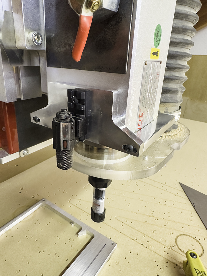
Nonetheless, the parts turned out nicely. After sanding the tabs off and doing a light finish sanding pass, I buffed the parts to a near-mirror finish and mounted the bracket onto the spindle motor, taking the place of the wooden prototype.
I went through the alignment process again, and when finished, I squirted a blob of hot-glue into the set screw holes on the laser to keep them from vibrating out of position. The hot-glue is removable in case I need to change the alignment in the future.
After completing this project I lay awake wondering if I had overlooked something. I thought about one possibility, which I call laser parallax. Adjusting the two setscrews on the laser obviously moves an optical element inside the laser. Is it moving the laser itself? A lens? I don’t know the answer, but I do have a potential parallax error in my positioning laser system. Will either axis shift as the spindle motor (Z-axis) moves up and down?
The answer to this question was found by testing the system. I scratched an X on my aluminum plate, then positioned my positioning laser exactly centereed on the X. Then I ran the spindle motor upward to the top of its track, and downward to the bottom. By observing the position of the laser beam relative to the cross-hair scratches, I determined that I was in big trouble. The laser remained perfectly aligned along the X-axis, but it wandered by an incredible 1/4 inch on both sides of the Y-axis scratch.
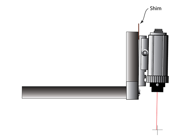
I marked the center of vertical travel on the spindle motor mechanism and aimed the laser at the cross-scratches. Then I moved the motor upward and downward while adjusting the two positioning set screws in the laser body. It was way off. I put various shims between the mounting rail and the motor body and tested it again. It got better, but it never got perfect. So I walked away for the night.
While studying a photo of the laser in the Amazon site, I noticed a fourth set screw in the device that I hadn’t noticed before. That set screw allows the body of the laser – a perfect cylinder – to be rotated inside its mount.
I removed the shims from the mount and put the laser back into its bracket. By rotating the cylinder I was able to move the laser in a circle on my aluminum aiming plate. By adjusting the other two positioning set screws I was able to move the beam until the spot of the beam did not move as I rotated the cylinder. This meant that I had found the optical center of the laser.
Once that center was achieved, I had only to position the entire bracket left and right until the beam crossed the X-axis scratch line. When it did, I tightened the screws on my bracket and tested the up-down movement of the spindle motor again. This time it remained perfectly centered on my scratched cross lines from top to bottom. Perfect!
I tightened everything up again, squeezed two blobs of hot glue into the set screw holes and started using my new positioning laser for my work.
I now have an effective tool for positioning with great precision on the CNC machine. I used it earlier today to align a long maple board on the spoilboard of the machine. I ran the laser to the edge of the board so it split the edge, half spilling over and drawing a line down the board. I ran the laser along the length of the board to ensure that it was straight before cutting it into a complex moulding.
I am extremely happy with this tool modification. I learned a lot and I added a laser that I am sure will be used many times while doing set-up and measurement on the machine.