

My plan was to write about some graphic arts subjects. I attended two terrific events related to printing recently, and I will write about my experiences – soon.
But instead, I want to write about my new lathe.
I have had a woodworking lathe for decades. It is a Sears & Roebuck machine built in 1953. I managed to put a small 1/3 HP motor on it, and I built a nice table for it back in the early 1990s. I took the lathe to a powder coating company and had them apply a blue coating on the machine. It’s really beautiful.
Somewhere along the line someone installed a three-jaw chuck to the lathe. This obviously came from a metal-working lathe. The problem is that they drilled it to the correct spindle size, and threaded it for the spindle a little bit off-center. So, for the past 30 years I have been troubled by a wobbly chuck, which made the lathe almost unusable. It is just awful.
Why I didn’t replace the lathe – or the chuck – in the interim, I cannot tell you. I just didn’t.
…until a month ago when I was invited to attend the Central Coast Woodturners club meeting. This coincided with the annular eclipse of the sun. We stood in the parking lot and admired a projection of the eclipse on a large sheet of paper. It was a pinhole and neutral-density filter combination that made this possible. This was a fanatic way to see the eclipse.
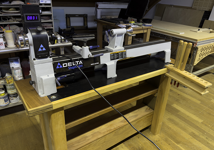
During the meeting, the president of the club announced that someone had donated a Delta lathe to the club, and the club wanted to sell it. The deal included an extended bed and a set of lathe tools, unused. I asked how much the club wanted, and after a vote, I was allowed to buy the whole thing for $300. I convinced a man in the club to deliver it to my house!
I took the lathe to my shop, removed the old lathe from its table, and attempted to put the new one on the same table only to discover that the new lathe is about 6 inches longer. That meant that I had to take the top off the table and put it in the wood stretcher! I built two wings of the same thickness as the original table, then affixed them with wood biscuits to the existing table, adding 10 inches to the table top. A bit of routing and some paint made it look OK.
I also decided that the new lathe would be too high to operate comfortably, so I shortened the table legs by three inches. Fortunately I had made the table with carriage bolts, and it came apart easily, then went back together just as easily.
The lathe had sat somewhere for quite a while, and when I attempted to put the drive belt onto one of the pulleys, it disintegrated. I ordered a new belt on Amazon.
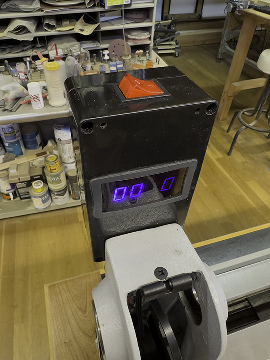
While waiting for that to be delivered, I decided to add an electronic tachometer to the machine so its speed would be indicated clearly (it has a fixed-speed motor with stepped pulleys). I have an ulterior motive also: I intend to replace the motor with a variable-speed motor someday. Having the tachometer on the machine will eventually be more valuable to me.
I ordered an electronic tachometer from Amazon, one that came with a Hall Effect sensor and a magnet. That arrived a couple of days later. I also ordered a plastic box to put the tachometer and power switch and wiring in. I studied the details of the sensor, placing it in various locations on the lathe, but it was too long. I simply couldn’t find a place where I could squeeze it that would be near the spindle pulley. So, I returned to the Amazon application and found a different Hall Effect sensor that is only three millimeters thick. I ordered that.
Meanwhile, I machined the plastic box to hold the components and made a terrible mistake cutting it on the CNC machine. I ruined it, so I ordered another one.
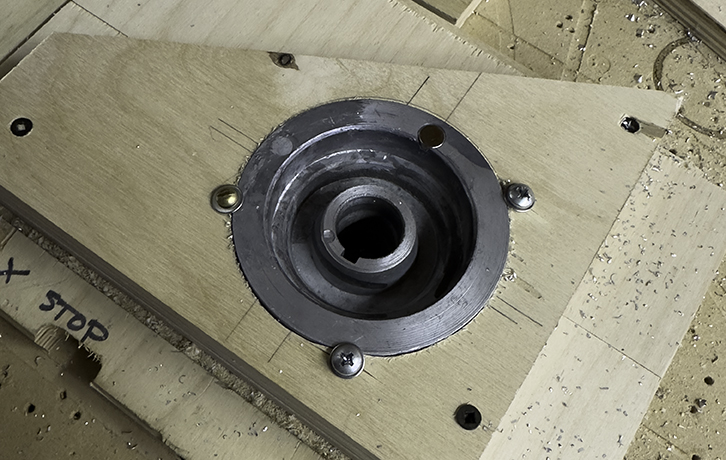
I also had to embed a fixed magnet into the pulley edge in a position where it would pass the sensor at 13mm distance. The pulley is cast aluminum, very light, but it does have enough body on the outermost ring to support a small magnet. To do this, I made a wooden contraption with a negative of the pulley machined into it, landing the pulley flush with the top of the jig for machining. Then I cut a shallow recess the size of the magnet in the rim of the pulley. The magnet is only a few grams, making its weight not much more than the aluminum I removed, so the net weight of the pulley is almost the same.
I couldn’t affix the magnet until I received the Hall Effect sensor because that sensor is triggered only by the south pole of the magnet, and I had no idea which side that was. I waited until the whole circuit was wired and running before rubbing the magnet against the sensor on each side to determine its polarity. Once that was determined, I put the magnet permanently into the pulley with epoxy.
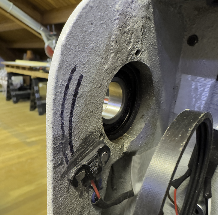
Wiring was moderately difficult because I had to run the wires where they would not interfere with the pulley, drive shaft and drive belt. I managed to squeeze the wiring into recesses in the casting to accomplish that, with the wire leaving the back of the machine through a waterproof fitting. From there, it goes only a few inches to the control box.
Hall Effect sensors are very clever. They come in a variety of shapes and sizes, and their basic function is to respond to a nearby magnetic field. When a magnet moves past the sensor, a reference trace in the circuit is affected by the magnetic field. That signal is amplified by a transistor, and sent to the tachometer, where it is “counted.” It is the counting of magnetic actuations per minute that is displayed on the tachometer.
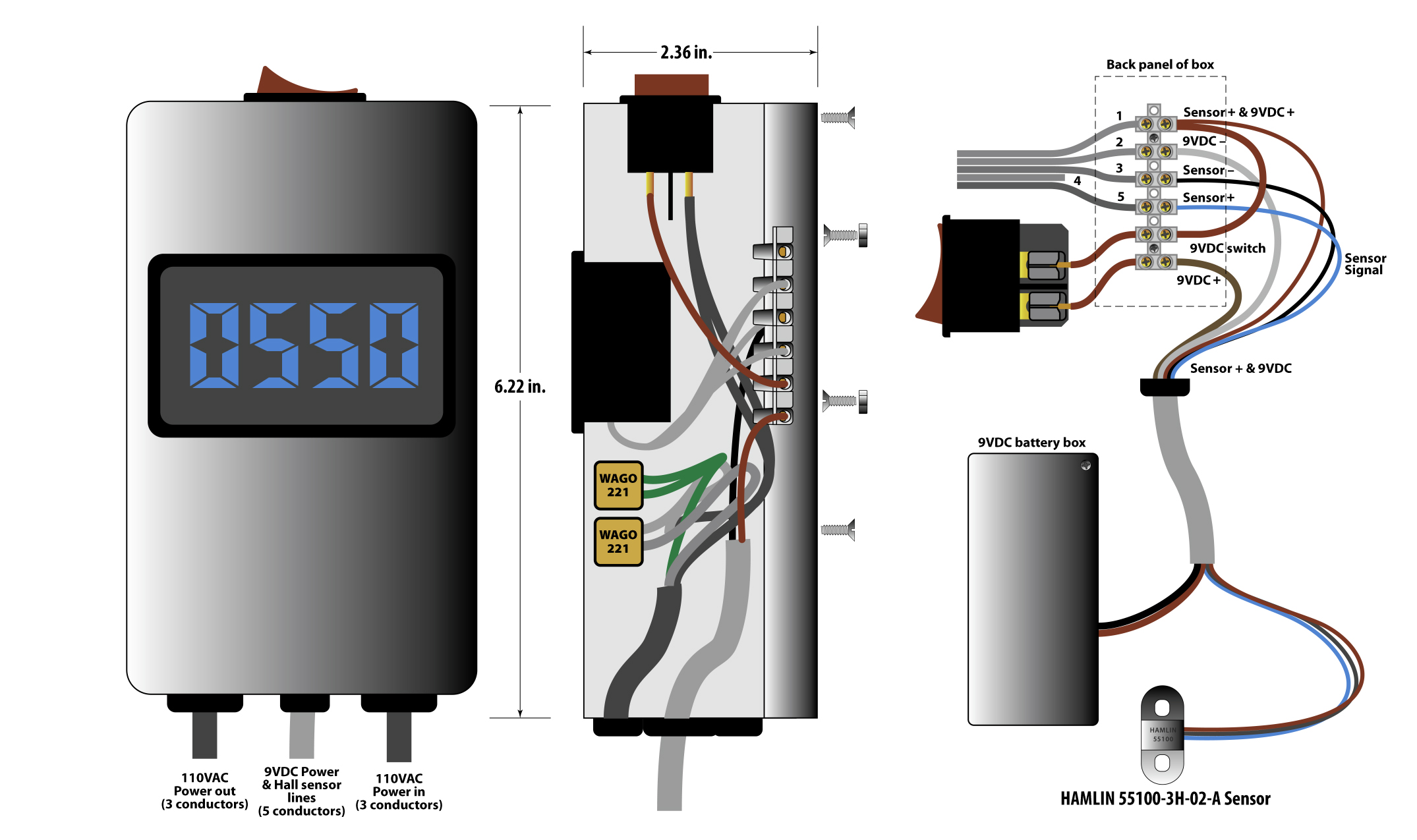
The sensor I found is called a Hamlin 55100. I measured the position of the pulley inside the lathe body, and marked its radius with a Sharpie. Then I mixed a glob of epoxy, and affixed the sensor to a spot that is exactly right to sense the passing magnet.
I wired both the lathe motor (110VAC) and the tachometer (9VDC) on the same switch (on opposite sides), so flipping the power switch activates both devices simultaneously. The tachometer circuit is powered by a 9 volt battery mounted in a box on the back of the lathe. I ran all the wires to the control box and connected them according to standards for their voltages.
Now I have a working lathe with a digital tachometer. It’s ironic that the speed must be changed by moving the V-belt, but someday when I put a variable-speed motor on the machine, that tachometer will be more useful.
(And, it was a fun project!)
Addendum May 23, 2024
I decided to make the conversion complete! I bought a DC motor conversion kit from Penn State Industries, and installed the new motor on my lathe. This makes it possible to change the speed from zero to 1,000 rpm without changing the drive belt.
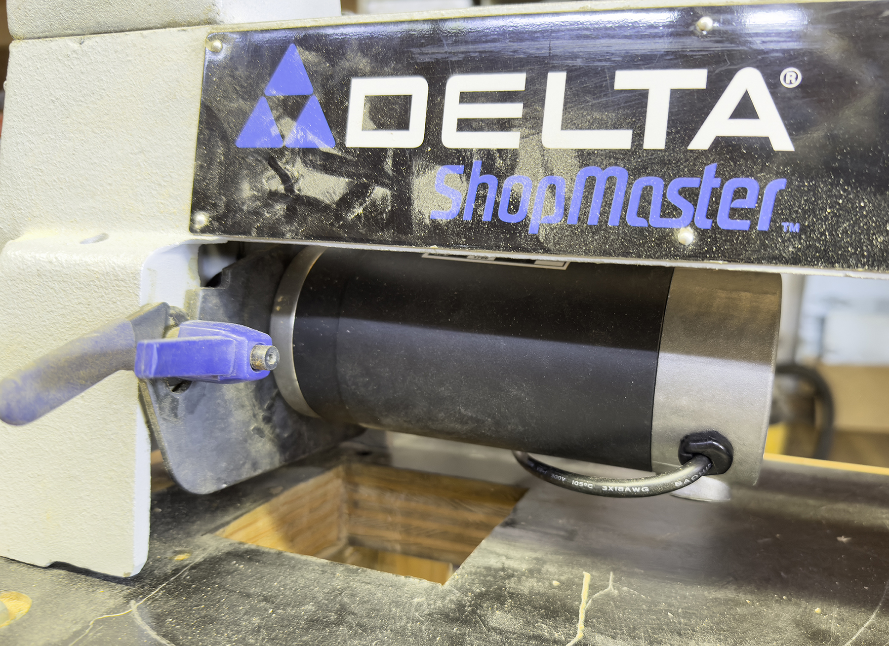
The kit comes with the new motor (more powerful than the one it is replacing), the speed controller box, and a template for drilling the mounting holes on the motor mount. I made a wooden template on the CNC machine, then used that to drill the holes in the existing motor mount. Minutes later the motor was in the machine and almost ready to go.
To finish, I had to remove the AC wiring from my original control box (shown at the top of this post) and install the new AC wiring where it was. Then I mounted the new speed control box to the left of my tachometer/power box, and turned it on. And it worked. But it was turning the wrong direction! I called the engineer at Penn State, who explained to me how to change the motor’s direction, and I got it going the correct way.
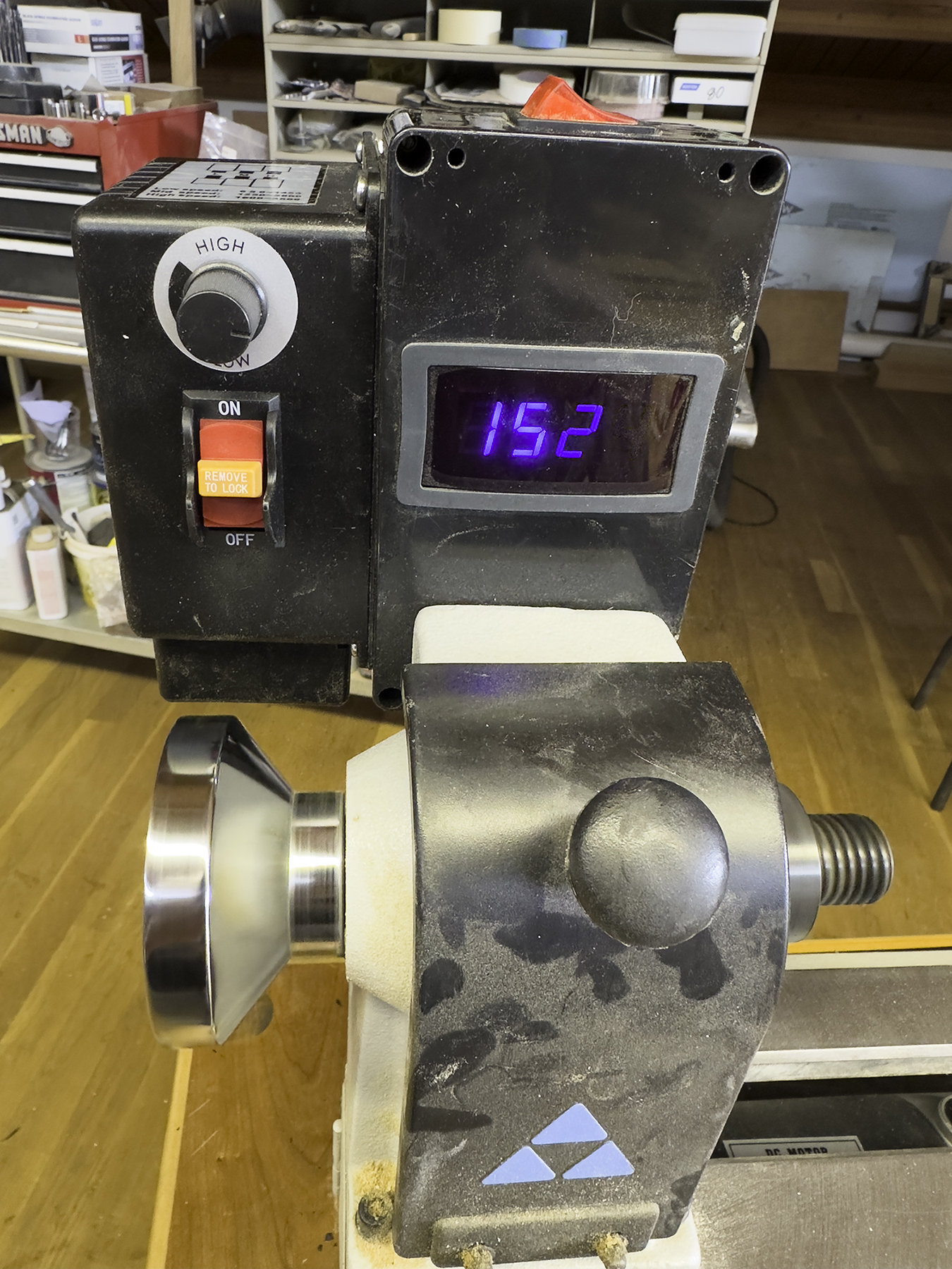
The engineer also told me how to set the low and high speeds on the circuit board inside the controller box, which I did. This makes it possible to get a tremendous range of speeds without ever changing the drive belt’s position on the pulleys.
Now the new lathe is complete!
Nice write-up, thanks for sharing. Reminds me of the time I first learned about Hall-effect sensors. Reference US patent 5,244,002. ?
https://www.google.com/search?q=us+patent+5%2C244%2C002
Hi Thomas,
Thanks for your comment. I have not reviewed patents on Hall-effect sensors. I will take a look.
Since I wrote that post I have not acquired a DC motor, which will give me variable-speed control on this lathe (it now works by changing a belt on pulleys). With the new motor, I will be able to control the speed better (and faster!) and might become a better wood-turner.
The new motor is also slightly more powerful, at 3/4 HP, where the motor that came on the lathe is only 1/3 HP. This will also help (I hope).
Best wishes,
Brian P. Lawler
The Blognosticator