
This is part 1 of a 3-part post on machining aluminum parts for a bicycle. Click here to read Part 2.
I have a gorgeous Superstrata electric-assist gravel bike.
I bought it a couple of years ago (actually four years ago, but there was a pandemic that interrupted the company’s manufacturing operation), and I have been enjoying it since then.
The Superstrata is a 3D printed carbon-fiber frame. Each bicycle is unique to its owner. When you order, you fill in a form where you enter your physical statistics – arm length, inseam, height, weight, distance from your knee to the floor, and a handful of other measurements.
Superstrata then puts that physical information into their computer and out comes a set of manufacturing instructions that drive their 3D manufacturing printers. After some considerable printing, sanding and finishing, you have a very special bicycle.
I took my bike to Burning Man last summer, where it performed perfectly. It has tires that are wide enough to run on the desert playa, and it is still a fast enough bike to be comfortable when traveling long distances. The range is estimated to be over 35 miles on a charge, which I have never tested.
At past Burning Men (I assume that’s the plural) I took my Bianchi commuter bike, which was comfortable, but occasionally got bogged-down in the playa sand traps.* That bike had a handy Pletscher bike rack and a set of panier bags. These allowed me to carry cameras and tripods on my sunrise and sunset photographic outings.
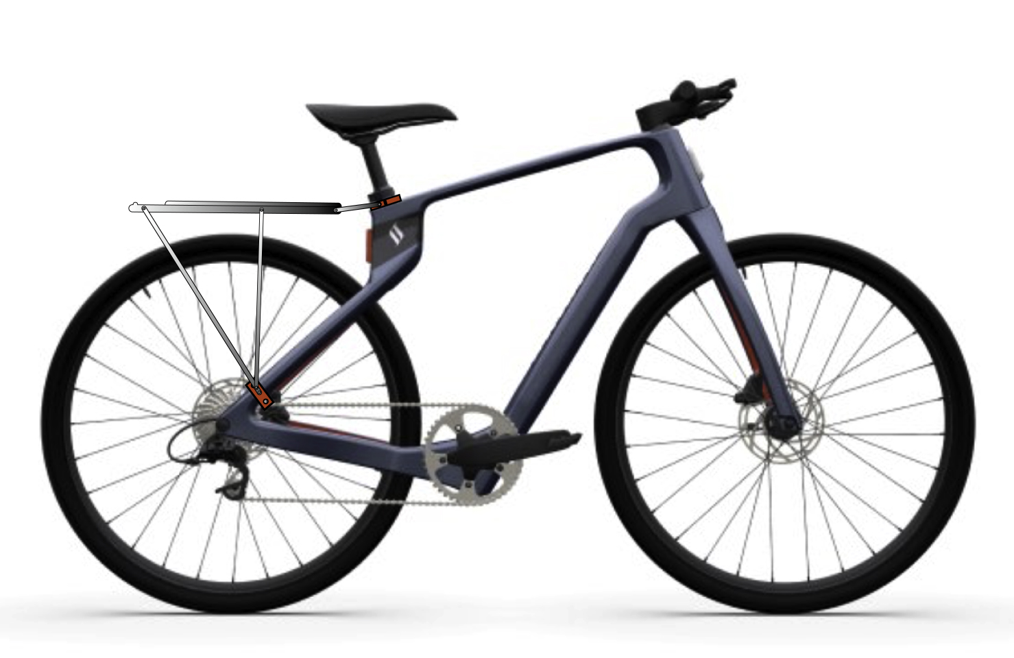
The Superstrata has no back rack, and has no attachment points for a rack. I was told not to drill into the carbon-fiber frame, as that could damage its strength. I need a rack, so I decided to make some clamps that attach to the frame in three locations, creating attachment points that will allow me to put my Pletscher rack on the Superstrata.
One of the nicest qualities of the Superstrata bikes is the organic shapes of the frame parts. The entire frame is 3D printed in one piece. The forks are printed separately, then the two are put together to make a bike. The constantly-curving arms from the seat to the rear hub change thickness and curve as they travel. I chose a good spot to attach the lower arm of the rack, and made a paper pattern that described that curve adequately.
I copied that pattern into Illustrator. Then I printed several versions of that pattern, cut them carefully with scissors, and tested them against the frame. Once I had the fit right, I designed the counter-clamp, which was a bit simpler. The top of the rack attaches at the circular seat post, where there is a convenient spot to put another pair of aluminum clamps that will attach to the seat post base. I am confident that it will be strong enough for my rack.
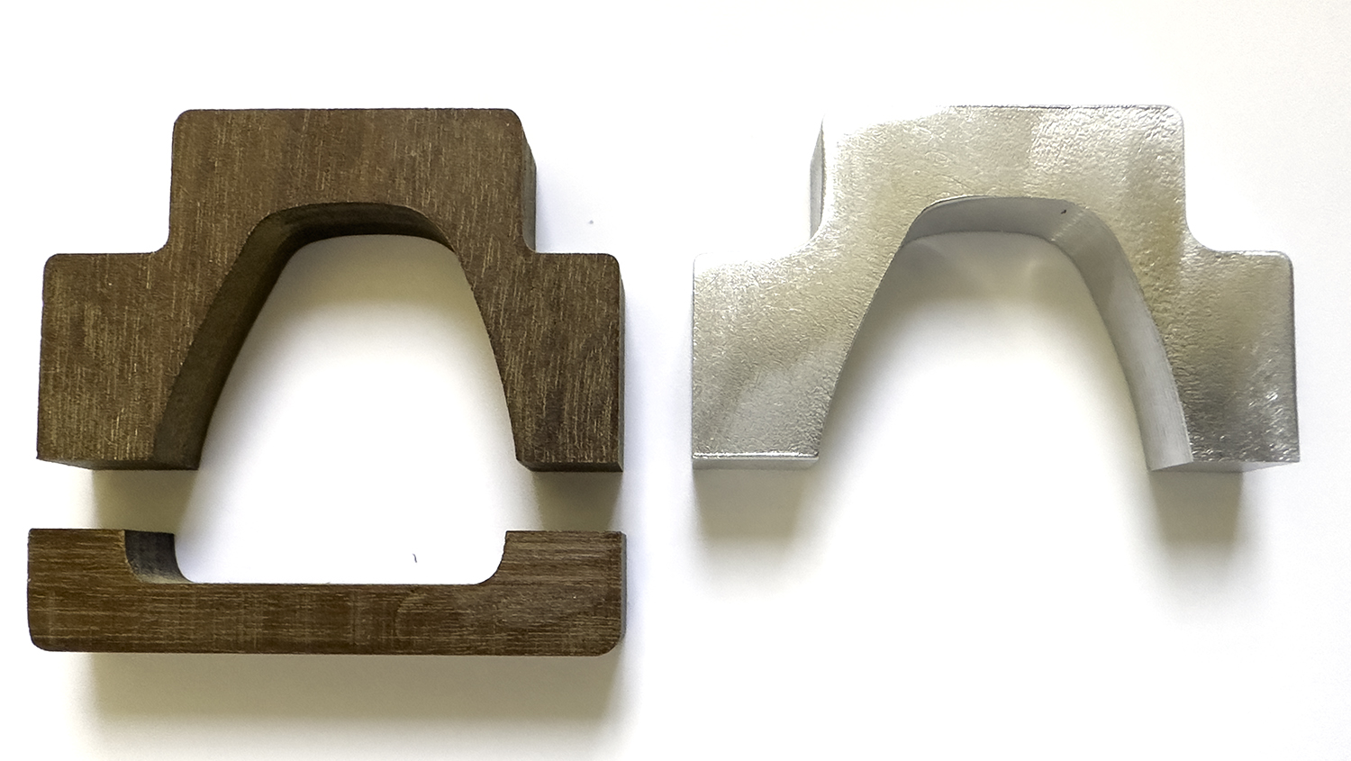
The next step was to move to the CNC machine and cut a prototype in wood. I have a good stock of Brazilian Ipé lumber (called Curbaril by arborists). I planed some of that down to 0.375 inch thickness, and machined a couple of parts in that wood. After a bit of sanding, I brought them to the bike and tested them. They needed some very small adjustments, which I made in my Illustrator file, then made my first aluminum prototype. This worked nearly perfectly.
Meanwhile, I ordered some stainless steel metric hex-head machine screws for these brackets. I needed several sizes and lengths. These were not available at our local Ace Hardware.
After that step, I went into my overdoing it in Illustrator phase. I drew each screw in tremendous detail, drew the screw heads accurately, and then used Illustrator’s 3D tools (better, but still not much to brag about) to extrude 3D versions of my parts to preview what they would look like.
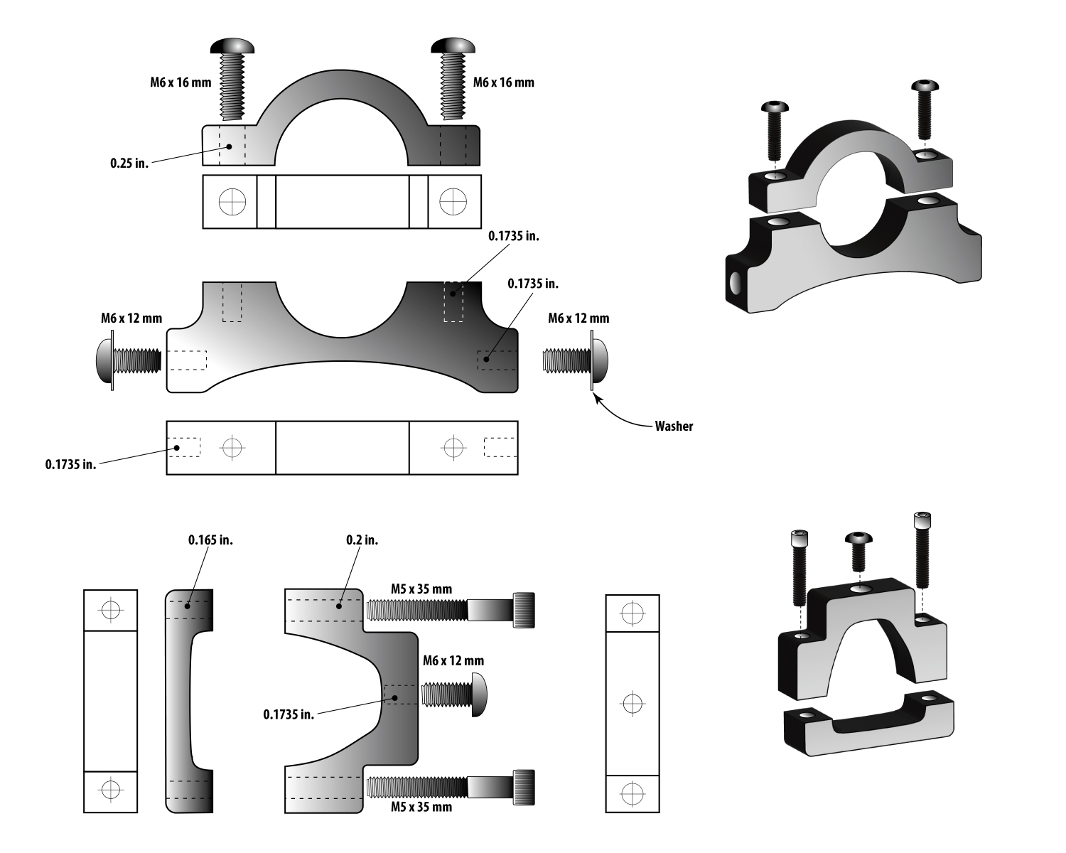
One can learn a lot while tinkering with an illustration. For example, the button-head screw heads are much larger than my original – estimated – drawing, and they would not fit the parts I had drawn. So I stretched the wings of each part to accommodate the larger screw heads, making the parts stronger in the process.
I’m ready now to machine the six parts in 0.375 aluminum. I have to run the CNC machine quite slowly to get a mirror finish on aluminum. That makes the parts nearly perfect when they come off the machine. I do a bit of buffing, and they are ready for use.
The other technique I have learned is to make a “gross” cut of the parts using a 1/4 inch cutter first, then change to a smaller diameter cutter for a very small final cut. To do this, I create an offset in Illustrator that creates a cutting path 0.005 in. away from the final dimension of the part. When those cuts are complete, I change the tool to a 1/8 in. cutter, and machine the final 0.005 along the perimeter of the part. This makes a smoother finish, and saves labor in buffing and polishing.
After the flat cuts are made, I turn the parts on their sides and insert them in a 90-degree work holder I made on the CNC machine. This is a hole in the spoil board with a T-slot board at 90 degrees to the tabletop. With various clamping boards I can affix small items to the work holder and cut their edges. I will use this technique to machine the holes in the edges of these parts – some for tapping threads, and others for allowing a screw free passage through.
I use a laser aiming tool on my CNC machine, which makes positioning relatively easy. I can move the laser to the edges of the aluminum parts to set the machine’s X and Y base positions. Then, moving in increments driven by software, I can drill and cut with extraordinary precision.
I will hand tap the threads in the holes that require threads, and then polish the finished parts to a smooth, mirror finish. Then they will go on the bicycle.
I’m starting to prepare for 2024 Burning Man by making my bike ready. Later this month I will work on the generator, which needs wiring on its water temperature gauge, and see if I can get its oil pressure gauge to work. I’ll report back on those things as I get closer to the Burning Man week. I hope it doesn’t rain this year.
I will report back as I make these parts and affix them to the Superstrata. I don’t expect any trouble.
*Playa sand traps are small areas of the lake bed where the soil is not compacted, but has the consistency of talcum powder. If you ride a bike into one, the bike stops immediately, and your body does not. I have had this happen numerous times, and have invented a medical condition that describes the result: the Bicycular Orchidotomy.
This is part 1 of a 3-part post on machining aluminum parts for a bicycle. Click here to read Part 2.