
In my last post I discussed making parts to hold a rack on the back of my Superstrata carbon-fiber bicycle. To read Part 3 of these posts, click here.
I have been machining those parts, and it has been a humbling experience!
On a CNC machine made primarily for cutting wood and wood composites (plywood, particle board, etc.), the cutting of aluminum requires that the machine be run more cautiously, more slowly, and with greater discipline.
Though I have been very cautious, I got a bit ahead of myself yesterday when I positioned the parts in a grouping that was very efficient for a scrap end of an aluminum plate I had on-hand. The machining went well for the first two parts, then I got into trouble. My error was in positioning the parts too close to one another, and in places where their support tabs would be cut off by subsequent cutting paths.
This was a serious mistake on my part, and it caused me to remember an adage in machining circles: holding the material is more than half the work!
I make almost all of my aluminum parts with a .25 inch single-flute cutter from Vortex Tools. That means that there will always be a quarter-inch channel around the periphery of the pieces I cut.
I knew this, of course, and I thought that I had planned for it in the positioning of my parts in the job. But, as my cutting continued – more than an hour into the process – I realized that I had lost control over two of my parts, and I still needed to make more passes to finish those parts. I stopped the machine and redesigned the cutting paths for those two parts to try to salvage the operation. It worked, to a point.
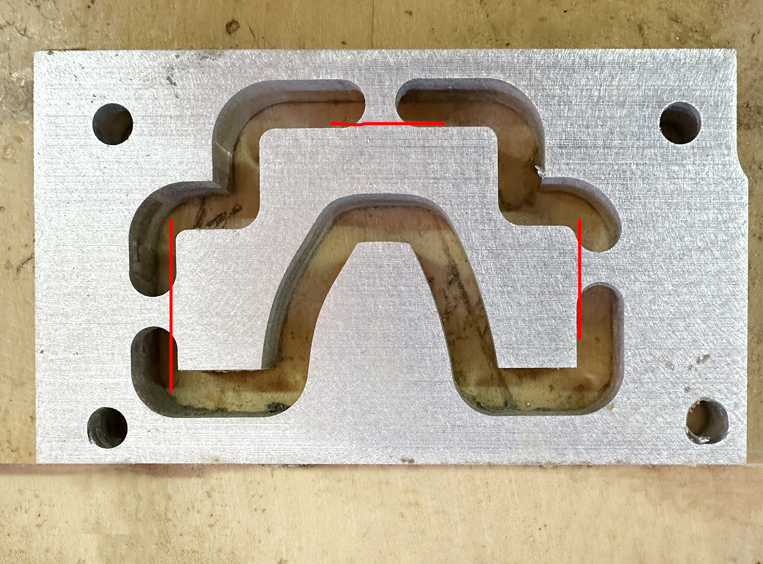
When cutting parts on the CNC machine, I usually insert small tabs along the edges of those parts that are left behind in the cutting steps. These tabs keep the machined pieces attached to the source material. At the end of the process, I cut the parts free by breaking or sawing the tabs, then I sand the remnants of the tabs off to remove them.
Yesterday, while preparing my file for cutting the parts, I put two tabs into the mix that would be cut off in subsequent cutting steps, leaving the original part unsupported. This is not acceptable, because I am pushing a rotating cutter up against the edge of a plate of aluminum with close to six horsepower of machinery, and expecting that little chunk of aluminum to sustain its tentative hold on the parent plate with just one tab!
In other words – I really messed up.
I restarted the project today, and I was be able to salvage the two parts by super-gluing them to the spoil board, a trick I learned from a machinist friend. The super-glue held on one, but broke free on the other, causing an unsightly divot in the surface of that part (not structurally significant). My parts are now cut, but still need to be drilled and threaded.

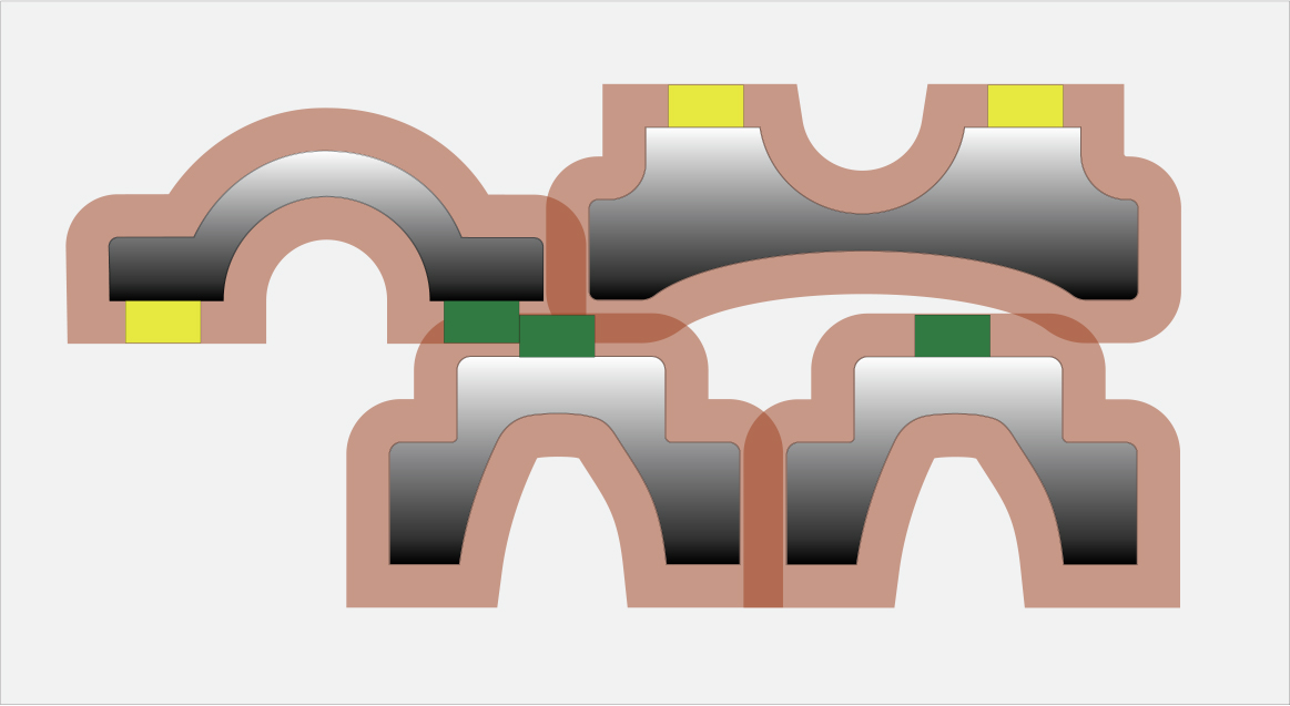
Here is what I did wrong: I positioned the pieces, nested together, into a small grouping that would fit into the area on the metal plate. I failed to make note of the tabs and their positions in the path of subsequent cuts.
What I will do from now on: Whenever positioning parts for nesting, I will draw an offset of 0.25 inch around every part, then analyze where those paths overlap in Adobe Illustrator. If they overlap in places without tabs, that’s OK; if they overlap in areas where there are tabs, then I will have to move the parts away from each other or reposition the tabs in some fashion to prevent those fatal intersections.
My future projects will come out better for this.
This is Part 2 of a three-part post. In the first part, I discussed designing parts to hold a rack on the back of my Superstrata carbon-fiber bicycle. To read Part 3 of these posts, click here.