
I have thousands – tens of thousands – of photos on film. These include 35mm negatives and slides, 120 film from my two Hasselblad cameras, and a boat load (a small boat) of 70mm sprocketed Ektachrome film. The 70mm era was when I was editor of Ballooning Magazine (1979-1984). During that era I was shooting with the Hasselblads (one was a 500 CM, the other was a 500 ELM) because many of my photos ended up in print, and I wanted the larger film to provide more room for enlargement and cropping.
The 70mm film made it possible for me to shoot more than 70 frames on a roll, in a special film magazine on the Hasselblads. This magazine was developed in the late ’60s by Hasselblad for NASA. The silver version of the back was the consumer model of the back they took to the moon several times.
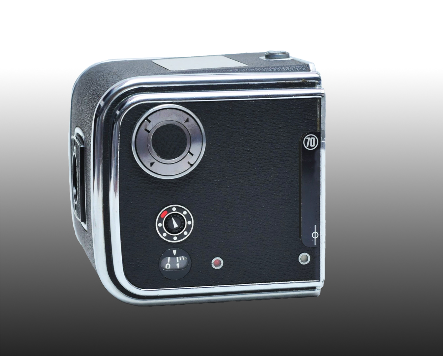
This is the 70mm film magazine for a Hasselblad 500 series camera. My film cartridges held about 70 frames of Kodak Ektachrome 64 transparency film.
I “rolled my own” as was often said in the ’60s, using a light-tight film-rolling machine that would take a 100-foot spool of fresh Ektachrome 70mm film, and then spool it down to smaller steel cartridges to put in the camera. At my graphic arts business we had an Ektachrome film processor, and I had a special reel for holding the long rolls of 70mm film for processing.
For those not familiar, a normal roll of film for the standard Hasselblad back allowed for 12 frames, max (there were other film backs with different formats). That meant changing film magazines constantly, which was a pain – even in the studio. On the surface of the moon, or on the balloon launch field, things happened too quickly for 12-frame magazines. I loved being able to shoot 70 frames without interruption.
Now, these many years later, the 70mm film creates a challenge for me. I am planning to digitize the entire archive, and to do so I am going to have to make my own masks and some equipment for re-photography. But, this also gave me an excuse to build my own copy stand. Though the image size is identical (51 mm x 51mm), the film itself is considerably wider than 120 film, and thus does not fit any standard scanning masks.
As for the stand itself, I certainly could have bought one, and I almost did, but I decided to make it myself, using my CNC machine, and some aluminum plate. And, I told myself that it would cost less, which of course was a bald-faced lie because it took me several weeks just to make the engineering drawings. Buying the raw materials has been fun, and it has enriched Jeff Bezos.
Over the years I have learned a thing or two about cutting aluminum on my CNC machine. The cutters are expensive, but they work beautifully. That is until you make a dumb mistake and tell the machine to break a $72 end mill in half in two seconds. Ouch!
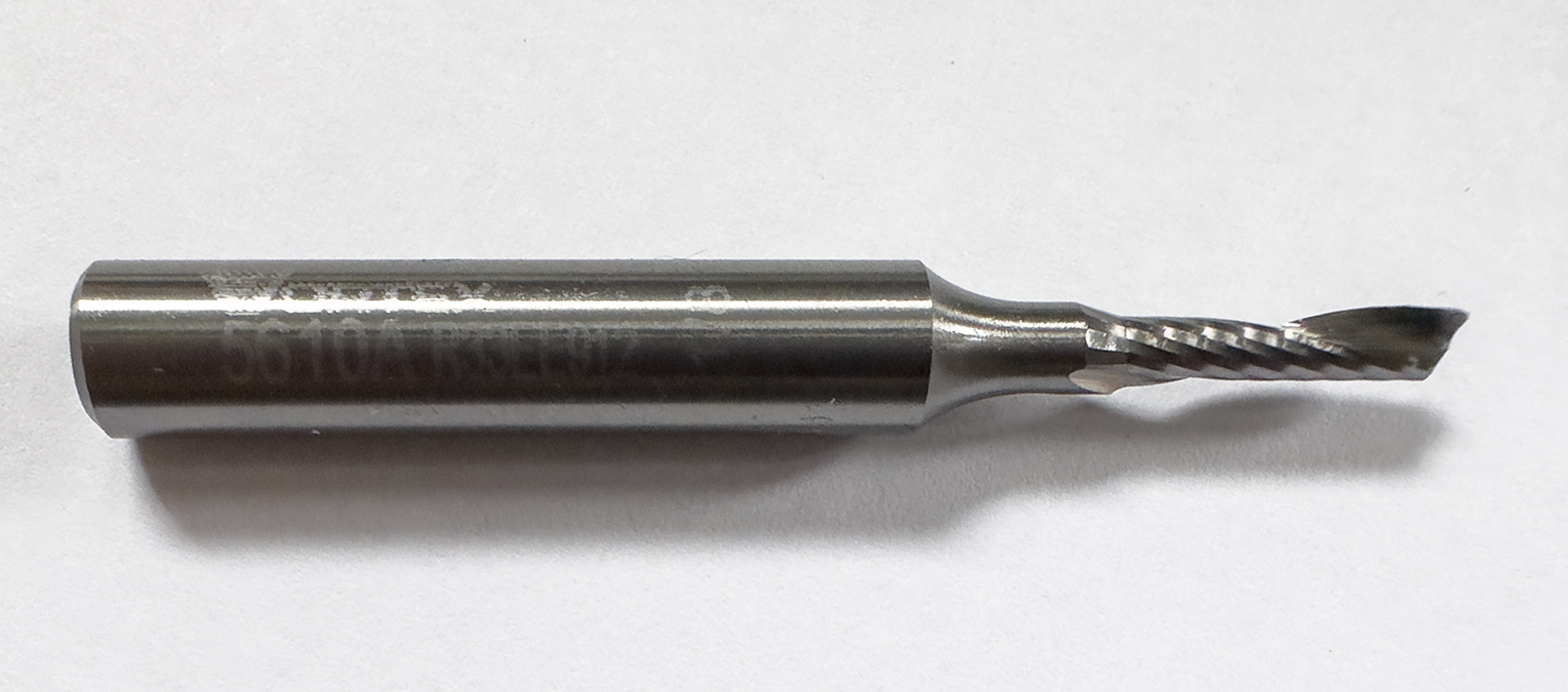
This is a single-flute aluminum cutting end mill. This one, made by Vortex, has a 0.108 inch diameter, and works very nicely for projects like mine. When they break, it’s a small tragedy.
Fortunately, I had two of that particular tool, so I cursed my stupidity and mounted number two (then I ordered two new ones for future stupidities).
Then I cut the aluminum parts, and began to build my dream copy stand.
I started with a section of extruded aluminum from 80-20, the clever company that pushes hot aluminum through macaroni dies to make pieces for fabricators worldwide. At the same time I ordered two smaller pieces to mount the camera – by attaching a camera bracket made by Really Right Stuff, the wonderful people who make the best tripods in the world (not sponsored).
I ordered the rack-and-pinion gears from Amazon, along with two knobs, a stack of bearings, 6mm brass rod, and various other small parts to put the whole thing together.
I machined a channel along one edge of the 80-20 vertical beam to accommodate my gear rack. This involved machining one of the grooves on the vertical beam wider to fit the steel gear rack (I don’t cut steel on my CNC machine). Then I drilled through the 80-20 vertical to drive screws through and into the steel gear rack to hold it in position.
When I ordered the 80-20 pieces, I had the ends threaded for 1/4-20 US machine screws. These will be used to attach the vertical to a small table, and the attach the Really Right Stuff camera bracket to the end of the support arm. The custom-cut parts from 80-20 are always precisely made, and perfectly cut. The table and most of the working parts of my CNC machine also were made by 80-20 (also not sponsored).
Most of my milling operations in aluminum are done with what is called a single-flute mill. This means that there is only one cutting wing at the business end of the cutter. When working in aluminum this is important to prevent hot aluminum chips from melting into the cutting surfaces of the end mills. My chips are varied, but very small, and always clean. That means that they are cut and thrown away from the material (I also use compressed air to blow the chips away).
I always make two outline cuts in my aluminum parts, meaning that I make a rough cut about 0.003 inch away from the final dimension. Then, when that is complete, I make a trimming pass to the final dimension. This usually results in a near-mirror finish.
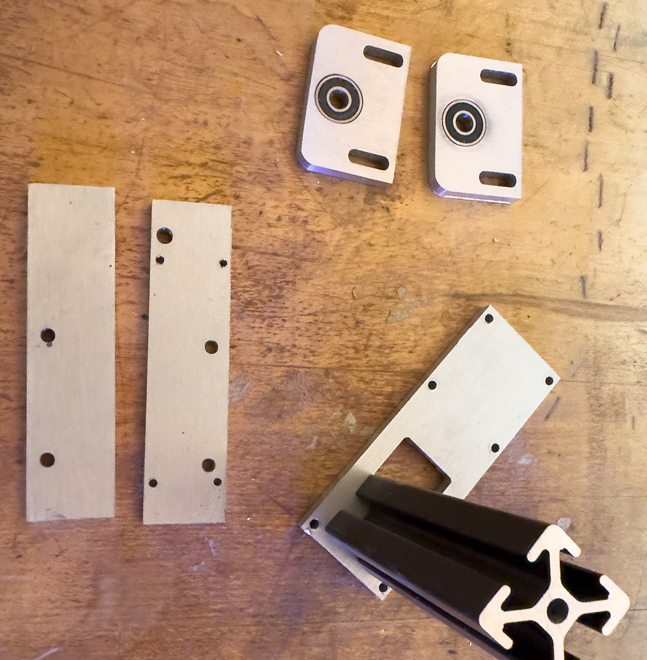
These are my aluminum parts after machining. The two bearing brackets (top) have the bearings in-place, and the front plate has the 80-20 aluminum extrusion standing where it will eventually be attached.
When machining anything on the CNC, the most important part of the job is how you hold on to the material. I recently rebuilt my machine to use devices called bench dogs. I drilled large holes on six-inch centers all over the spoilboard, into which the dogs are placed. One type of bench dog is a solid steel pin with one flat side. The other side is a pin with a threaded rod going through it. On one end of that rod is a brass bar, and on the other there is a hex head. When I use these, I tighten the brass bar to squeeze my material, holding it in place.
For this I also cut some scrap plywood at a 10 degree angle to hold the aluminum plate on top of the spoilboard. The slightly-sloped edges force the board downward as I apply pressure along the edges. I attach the aluminum plate to that scrap material with wood screws. Rule number two in CNC work is never hit the screws with the $72 cutter! (I didn’t, but I have in the past).
Several hours later I had cut most of my aluminum parts. These came out beautifully. The only problem I had was drilling tiny holes into the edges of two plates. This kind of work is always challenging, and I had the usual difficulty this time. I stand the cut pieces in a vise, then I bolt that vice to the spoilboard using the bench dogs. I use an aiming laser in the spindle to position the edges of the material exactly. Then I move the spindle under computer control half-way across the material. Then I insert a centering drill into the spindle and make a program to cut the three vertical holes in the material.
Once all the parts were complete, I had to thread about half the holes to put threads inside. This is tedious work. I managed to get all of them threaded without breaking a tap (a minor miracle for me!). With the threads cut, I was now able to put the parts together.
The most difficult part for me was connecting the 45-degree 80-20 bar to the square arm that holds the camera on my stand. 80-20 does not offer a 45-degree attachment device, instead suggesting side plates. Though these would work, they will not fit into the device I have designed. Instead, I made a jig, mounted the two aluminum bars to that jig, the drilled 45-degree holes through the pieces. After that, I threaded the resulting holes and put M5 cap screws inside to hold the pieces firmly in place. This worked well, but does not offer any adjustability.
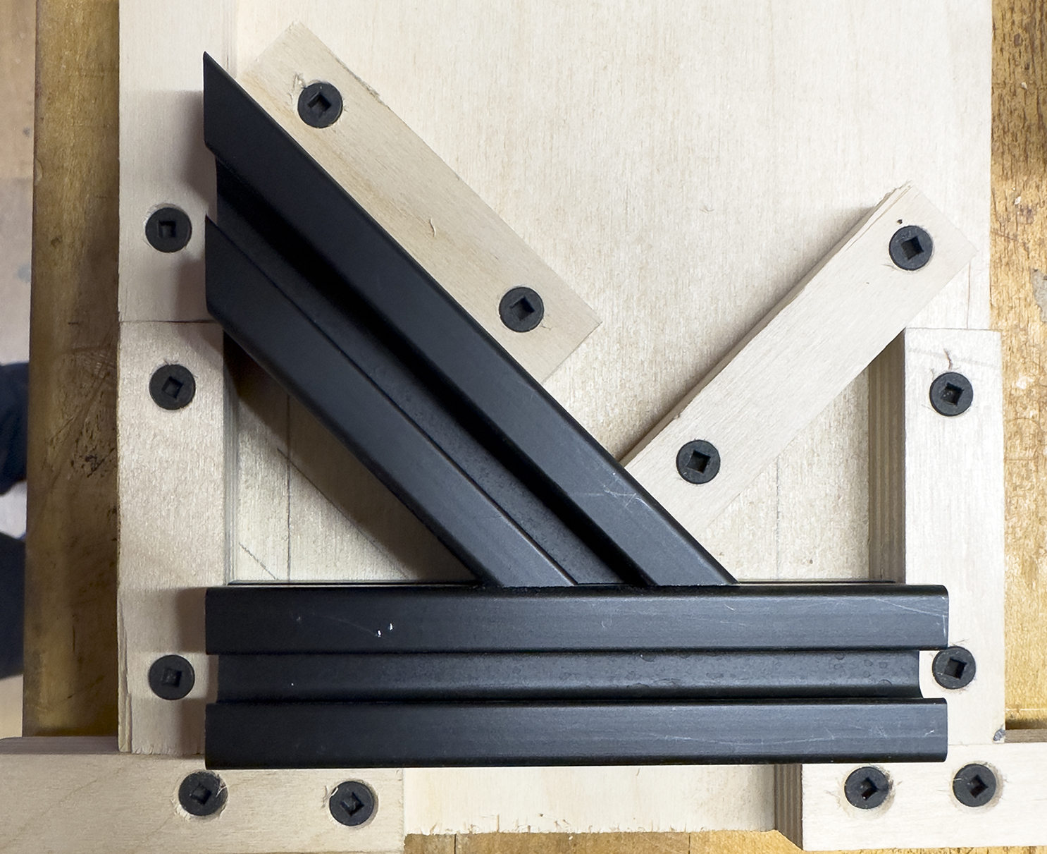
This is my 45-degree angle drilling jig. It holds the 80-20 aluminum bars in position while I drill holes to thread and later, hold them together accurately.
With the pieces complete, I sanded the parts, brushed them with steel wool, and painted them flat black. This was done to reduce reflections.
I mounted the tall vertical post on which my camera mount slides to a sheet of nice plywood, faced with black Masonite-like material (Formica would have been better). After mounting the post, I realized that it is sturdy, but that there is not enough connection strength at the base. I ordered some 90-degree L-brackets from 80-20, and will add those to the base connection when they arrive. I believe that this will add the additional sturdiness I need.
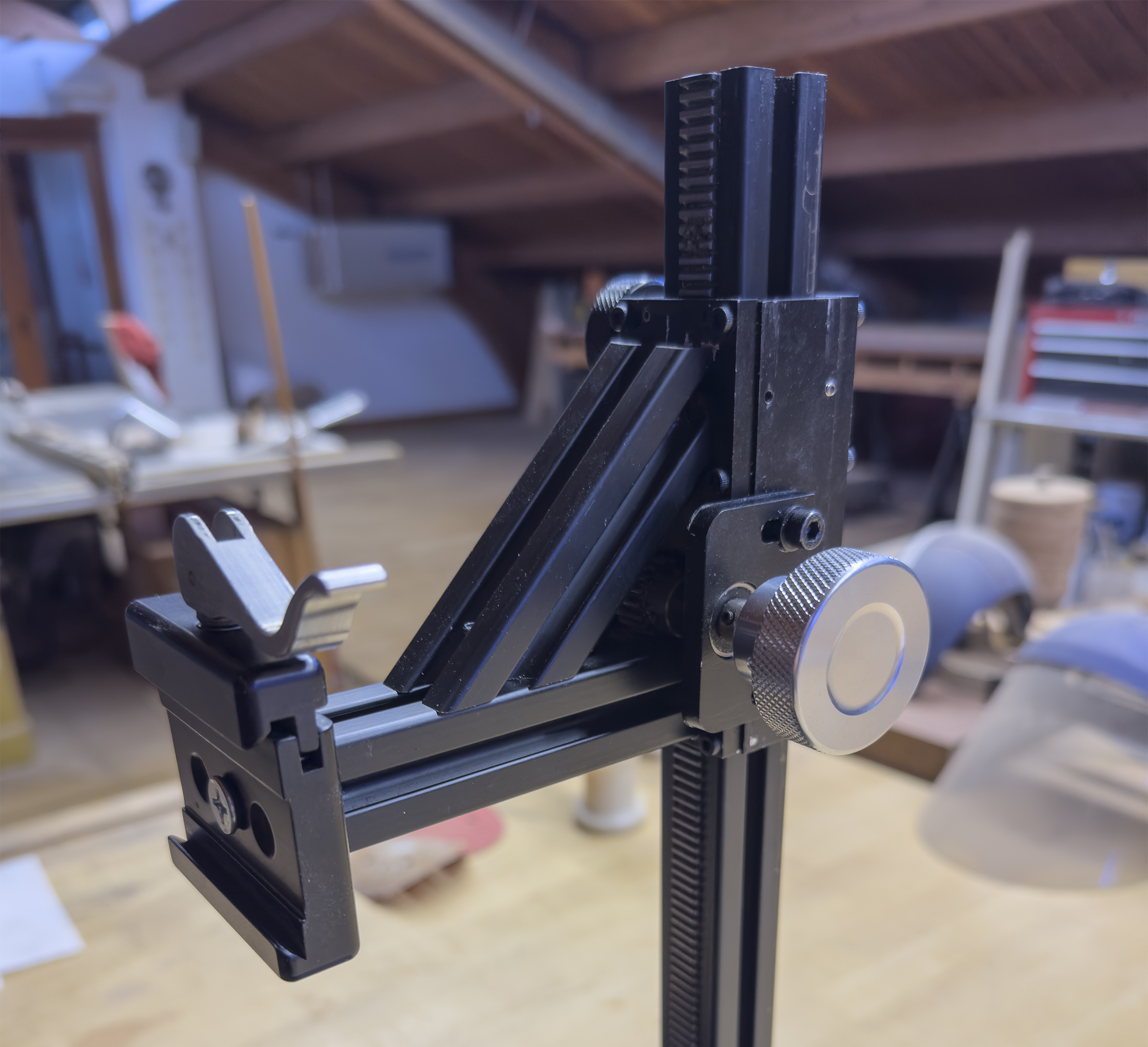
This is the finished camera bracket mechanism on the vertical post of my camera stand. It features one knob (silver) for raising and lowering the camera on the rack gear in the vertical post, and another (black) for tightening the mechanism in-place. It works very nicely.
My Big Plan is to begin digitizing my film soon. I’ll write more as I get going on the project. There will be a lot to learn here!
To see more on this project, and to download PDF of the engineering drawings, click here.