

In previous blogs I have described how I have designed things in Illustrator, then built them out of wood in my shop. The shop in question is located in my friend Jim’s barn. We consolidated shops in 2005 when I moved into a small house where there is no room for large power tools.
Since then we have expanded the shop to include several stationary power tools and a very large work bench and assembly table that has electricity and compressed air delivered to its perimeter. I have added digital micrometers to two of our tools – one to the router table, making it precise to 0.001 in., another to our 12-inch planer, adding the ability to dial-in similar precision to cuts we make on that machine.
Moving deeper into the digital domain, last month we installed a large CNC router table, and we have been learning the ropes of computer-controlled routing since then. The CNC machine is a product of a Washington state company called Avid CNC. They sell kits for the do-it-yourselfer to make a CNC machine of your own. The parts are well-made; the precision of the machine is extraordinary.
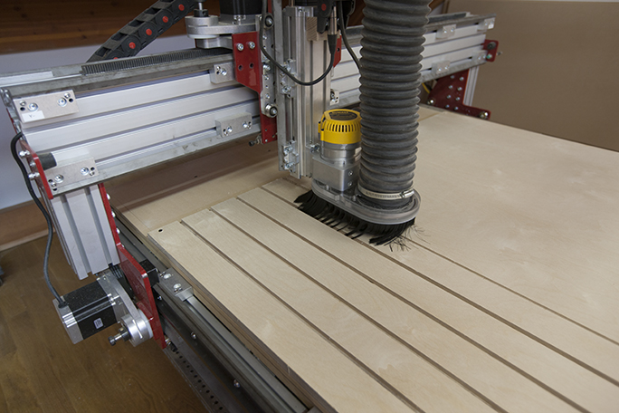 This is the CNC router, built from a kit made by Avid CNC. At the moment of this photo the router was cutting T-slots in a sheet of 3/4 in. hardwood plywood. That plywood sheet will become a hold-down board for future projects.
Once the machine was assembled, which took the better part of two days, it was ready to run. We entered the learning mode, where we have been for several weeks. We have learned that the machine will do exactly what you tell it to do – even machine right through itself, if you give it the wrong instructions.
It’s a very powerful machine, using four NEMA 34 stepper motors to control the movements and position of a DeWalt 3.5 HP router (replaced twice since with more powerful motors).
We run the machine with a program called Mach3, which is probably the most common machine control software in the industry. That software can be customized to control a wide variety of CNC devices. Ours is pretty simple – left-right (X), back-forth (Y), and up-down (Z). But within these three seemingly simple axes are a world of complexities: cutting speed, spindle speed, plunge speed, cutting depth, number of passes, step-over settings, tabs, and much more.
CNC machines of all types use a control schema called G-code. G-code is text, thankfully, and it’s pretty easy to interpret. Here is a snippet of G-code:
G0 X0.0000 Y0.0000 Z0.8000
(Closet shelves 3)
T1
(End Mill {0.25 inches})
F150.0
F30.0
S6000
G0 X9.0267 Y4.7822 Z0.2000
G1   Z-0.2500 F30.0
G1  Y17.5546  F150.0
G1 X9.0767
G1 X9.0765 Y4.7744
G1 X9.0753 Y4.7632
G1 X9.0728 Y4.7555
G1 X9.0666 Y4.7520
G1 X9.0559 Y4.7498
G1 X9.0435 Y4.7503
G1 X9.0345 Y4.7530
G1 X9.0304 Y4.7559
G1 X9.0277 Y4.7663
G1 X9.0267 Y4.7822
G1 X8.9267 Y4.7810
If you study the G-code, you’ll begin to recognize its instructions. The top line tells the machine to go to X0, Y0, and 0.8 Z, which is eight-tenths of an inch above the work surface. This is “home” for the X and Y axes, and a safe margin above the material so it doesn’t start cutting too soon. The T1 is a definition for Tool 1 (some machines have multiple tools). Ours has only one, and in this case, it’s defined as an end-mill (a simple two-flute 1/4 in. diameter router cutter). The next two lines are X and Y cutting speed (150 in. per minute or 2.5 inches per second, which is pretty fast), and a plunge speed of 30 inches per minute, which translates into one-half inch per second, also pretty fast. The S stands for spindle speed, which in this case is 6,000 rpm.
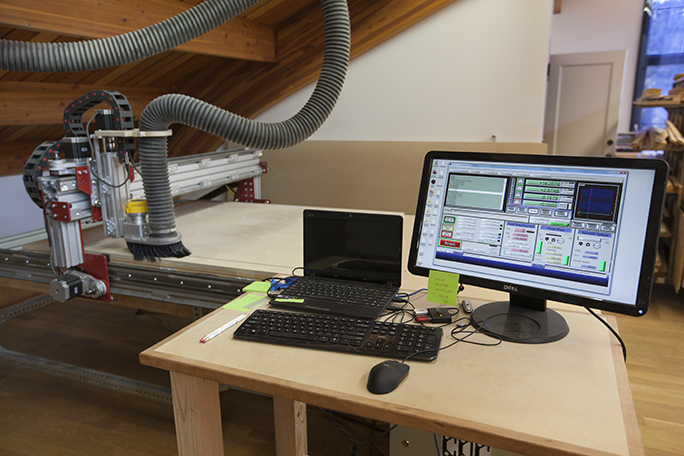 The router is controlled by a Windows PC, running two programs: V-Carve Pro and Mach3, both of which are necessary to do CNC design and machine control.
Then the work begins, which an instruction to move 9.0267 inches along the left-right axis, 4.7822 inches along the back-forth (Y) axis, and to hover above the material at 0.2 inches (it will begin cutting there). Following these instructions, we learn that the machine is starting a cutting path at this location because it immediately plunges the cutter .25 inches down (below zero Z), then moves to a new location along the Y axis only (a straight line), then a similar cut along the X axis, and begins a complex “curved” cut described by hundreds of lines of X-Y code positions.
Machines like this don’t really cut curves, they step in both X and Y directions in small increments, making the effect of a curve in the material being machined. It’s equivalent to the effect of applying a raster to a curve in Adobe Photoshop. The curve is converted from a mathematical entity into a series of pixels on an X-Y grid defined by the resolution of the photo. In the CNC software, that raster grid is 0.0001 in., though the resolution of the machine is closer to 0.002 inch. The stepper motors can move in micro-steps, essentially half-steps that can increment the cutter between two poles of the stepper motors.
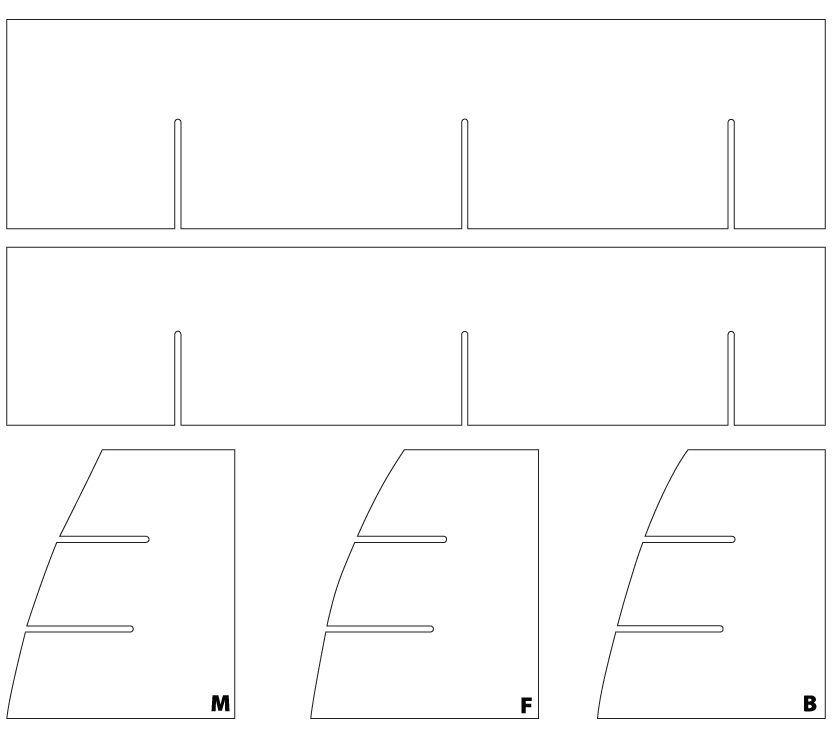 These are parts designed in Adobe Illustrator for a set of interlocking shelves I made for a cabinet in my camper van. I drew them at actual size in Illustrator, imported the file into V-Carve, and machined the parts in Baltic 1/4-inch plywood.
I suppose, with a bit of practice, one could write G-code by hand; it would be like writing a photo’s pixels with a word processor. The consequences of error are much greater when you are running a multi-horsepower machine with a spinning blade into a block of wood, or worse – part of its own aluminum or steel superstructure. Oops!
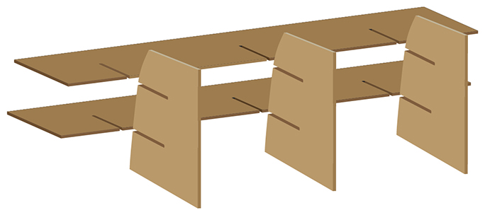 This is the exploded view of the shelves I drew in Adobe Illustrator. I used the 3D extrude tools in Illustrator to convert 2D art into 3D representations.
To build the G-code, we use another program. The program we have chosen is a Windows-only application called V-Carve. It’s a very popular CNC design tool for a variety of uses, and it has the ability to import Adobe Illustrator (.ai) files directly. I experimented with a similar program for Macintosh called MESHCam, which is nice, but it lacks many of the capabilities of V-Carve on Windows, and it requires the intermediate step of exporting DXF files from Illustrator (no big deal, but it’s an extra step).
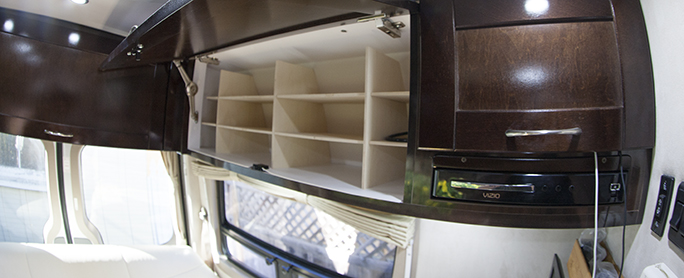 …and these are the finished shelves in the cabinet of my van. They provide easy storage for our clothes when we go out camping in the RV.
The way V-Carve (and similar programs) works is to declare a material size and thickness, and the origin X,Y as one of the corners (three-dimensional space can be reassigned on these CNC machines).
Once the material is defined, then cutting paths can be drawn in V-Carve or imported from Adobe Illustrator. Once those paths have been imported, they can be assigned to cutting tools, with cutting speeds and cutting depths assigned. When complete (and I am glossing over a lot of detail here), V-Carve generates the G-code for the project, and you load the G-code into Mach3, and you make your parts. This, after mounting the material solidly to the cutting table of the machine. You’re in big trouble if you fail to secure your work to the table.
Once it gets going, the CNC machine is a delight to watch. It roars around the material raising and plunging its cutter into the material and making a huge amount of sawdust where there once was solid material. It also makes a lot of noise. In the coming days I will write about some of my projects, and will show examples of how I have been using the machine to make practical things from Adobe Illustrator designs.
Hi Brian!
This was a very useful article! I was wondering if you used only Mach3, vCarve and Adobe Illustrator as the main softwares to run the entire process. Did you have to use any other design software, such as AutoCAD?
Any answers will be great help! Thanks!
Hi Nancy,
So far I have been able to do everything I need with Adobe Illustrator. I know that a true 3D program like AutoCAD would give me much more control, but I have never taken the time to learn that program. It would be a much more thorough approach to design-to-manufacturing than the technique I now use.
The advantages include being able to see whether a design works from every angle. The way I do it now is to test the patterns in my head, and occasionally I build one version in less expensive plywood before committing to oak or other costly material.
Solid Works is another one to consider because it can also preview the cutting, showing anything that could cause a collision on the CNC machine. I have made a few costly mistakes on the machine by telling it to cut through itself, for example (it’s happy to do that, but the way).
Best wishes,
Brian P. Lawler
Or you can use CAMotics, a free open source program, to preview the cuts, to make sure everything is ok before cutting.
Dear Vincent,
Thank you for the information about CAMotics. I have been looking online to see if I can use it. I appreciate your contribution to the conversation.
Brian P. Lawler
I use CAMotics a lot to preview cuts. Checking out VCarve as my usual toolpath is Illustrator->HeeksCNC -> CAMotics -> CNC mill. Heeks is by far the weakest link.
While any kind of lumber router over 3 HP can be employed in the router kitchen table, I favor the actual high run kinds for that application because you don’t have to stress about the way large they may be and also you may as well include as much strength useful as you want.
Hi Dora,
I am not sure exactly what you are referring to, but I think you mean a router more powerful than 3HP. In that case I agree. I recently replaced my 2.x DeWalt router with a new Bosch 3HP model, and it has power to spare.
There are much more powerful, and quieter router motors available, but they are much, much more expensive than the smaller units.
Another benefit of the Bosch is that it fit the bracket I had already with no modification.
Best wishes,
Brian P. Lawler
This was a very useful article! I have a question: Did you have to use other design software, such as AutoCAD?
Hi Alexander,
I don’t have any experience with AutoCAD, but it will work with the tools that I use. My usual technique is to design in Adobe Illustrator, then open my Illustrator files in V-Carve, the software that writes the G-code I need on the CNC machine.
Brian
Thanks for sharing and I love Adobe Illustrator!
There is an Adobe Illustrator plug-in called ImagePaint GCode Pro from http://www.amazoncanvas.com that would make it so easy to do 2D CNC work entirely from within Illustrator.
A bit late, but you will probably find this tool useful
https://diegomonzon.com/illustrator-to-gcode/