
Now that the Smyth machine is working, I decided to take on a new project.
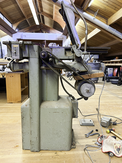
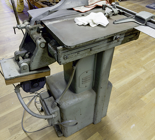
Last fall I offered to restore a 1960s era Hammond Glider TrimOsaw for the Shakespeare Press Museum at Cal Poly. This machine is best described as a precision table saw for cutting metal type, Linotype slugs, Ludlow slugs, and similar materials used in typesetting. The machine has a 7-inch blade and a precision micrometer miter gauge for setting the line length in one-point (0.0138 in.) increments. It also features a precision blade lift that can be adjusted in 1-point increments.
In every other way, it’s a small table saw.
The company that made it, Hammond Machinery Company, is still in business in Kalamazoo, Michigan. They now make industrial abrasive machines for smoothing parts and surfaces. They are still in the same building as they were over 100 years ago when they began making machines. Unfortunately, unlike the Smyth company, they don’t stock parts for their 20th century printing industry machines (I asked).
With the help of my friend D.K. Philbin, I moved the machine from Shakespeare Press Museum at Cal Poly to my shop, 10 miles away.
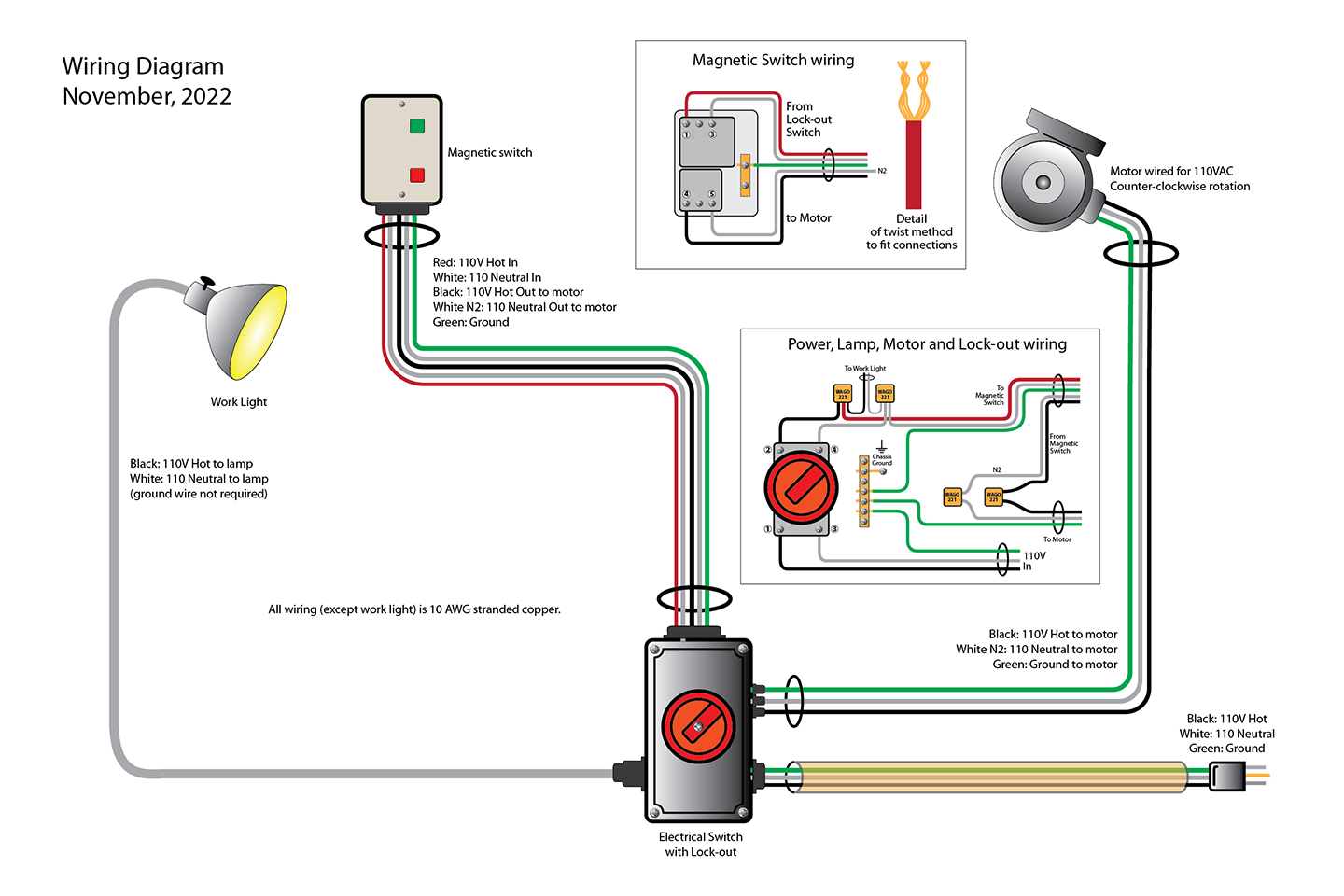
Once there, I tore it down and began work. First I removed the electrical work that had been re-done in the 1970s. The original saw had a 240 volt connection, and then a transformer to power the 110V work lamp on the machine. I found this ironic since you don’t need a transformer to get 110 volts on a 240 volt circuit (you take one hot leg and the neutral, and you get 110 volts!). I put the old transformer into e-waste.
The machine had been painted with a brush in an awful green-gray color. I found the original color underneath, and I bought some Cedar Green paint that closely matches the original color of the machine.
The saw is made of cast iron, and it weighs a healthy 400 lbs. It’s very hard to move, even using a hand truck. Once at my shop, I found that lifting it with an engine hoist worked, and that made it possible for me to do it alone. My first order of business was to mount it on a rolling base that will forever be under the machine, allowing it to be moved when necessary.
The wiring was functional, but not “to-code” – meaning that someone had put solid copper wire in flexible conduits, used the wrong colors of wire, and had simply ignored the requirement for a ground wire to the motor, grounding it to the frame and the building circuits.
The V-belts were old and tired. The electric motor was in serviceable condition, but it was mounted on a block of 8 x 10 inch wood with bolts. This made no sense, so I removed it.
The working surfaces of the machine – its tables – had been abused by workers who had put heavy, sharp objects on top many times, putting hundreds of small dings into those surfaces. All of the unpainted surfaces were covered with a light rust. That’s where I started on the cosmetic work.
Using silicone oil as a sanding slurry, I attacked those surfaces with an orbital sander mounted with emery paper. In successive passes I smoothed those surfaces down to a nice sheen, and I removed much of the damage. When finished, I applied a paste wax to those cast iron surfaces to make them more resistant to rust, and to make them slippery, which enhances their smooth and safe operation.
I tested the motor, but it didn’t work correctly. It would start, run up to speed, and then slow down, over and over. Alternating-current induction motors like these are surprisingly simple devices. They have very few moving parts (a rotor and a centrifugal switch) and almost nothing can fail inside other than the centrifugal switch and the capacitor. The capacitor tested fine, so I adjusted the centrifugal switch. It worked better, but still not perfectly.
The motor needed a new mount to replace the block of wood that held it for 60 years. I machined one out of aluminum plate on my CNC machine, and then painted that plate to make it look nice. Once the paint was dry, the motor was ready to go back on the machine.
I took the motor apart four times, each time making a different mistake in reassembly. I drew a wiring diagram of how it was connected when I started, then consulted the wiring diagram that is printed on the inside of a metal plate on the motor. I kept wondering about the brown wire, which was connected to one post and which allowed the motor to run on 110 volt power. The diagram showed that wire connected to a different lug. I studied it, and determined that it could not be connected there, so I left it where it was. Surprisingly, the diagram printed on the motor itself is in error.

The motor was of an era when the electrical code did not require a separate ground wire from the motor to the circuit. I suppose the manufacturer assumed that the motor would be bolted onto a metal plate, which would be bolted onto another metal plate, and that to the frame of the machine, all providing electrical and mechanical grounding (They obviously didn’t consider the 8 x 10 board that held the motor to the machine.) I added a separate ground wire to the motor conduit, and attached that to the motor body, and then to the electric box on the back of the machine.
I replaced the V-belts with two of the same size and brand, ordered from the local auto parts dealer. Then I removed the beautiful TrimOsaw nameplate from the front of the machine with extreme care. It was affixed with rivets to the cast iron body. I ground the heads off the rivets with a small portable grinder, and eventually the nameplate came free with minimal damage.
Part II, where the saw comes back to life, is available here.