
This is the second part of my obsession story. To read the first part, please click here.
And that’s where my odyssey began. Alternating current induction motors use the frequency of the line power (60 Hz in our case) to set the speed of the motor. To change speed, one must vary the frequency. For that there is a relatively new technology on the market call the Variable-Frequency Drive. These devices, all solid-state, are miraculous for this purpose. VFDs can be obtained that convert single-phase electricity to three-phase (solving one of the great machine shop problems of the world), and converting three-phase 60 Hz to three-phase almost-any Hertz for motor control.
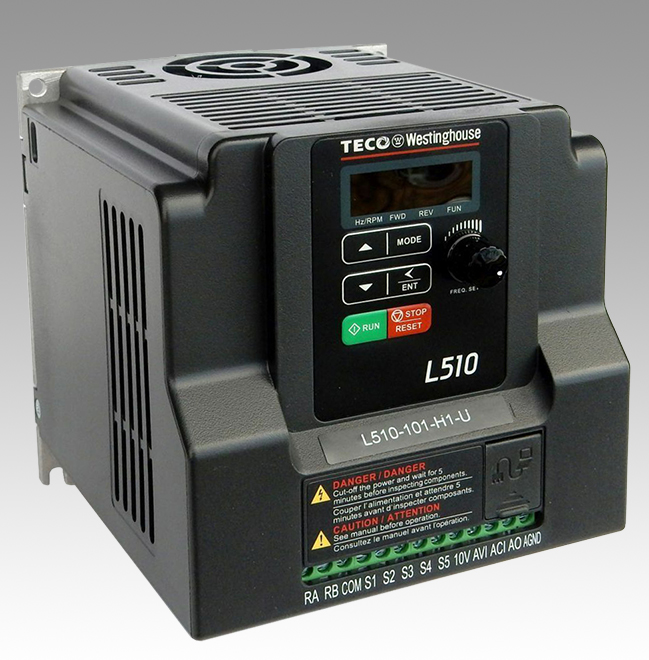
I researched these and bought one made by a Taiwanese company called Teco, a company affiliated with Westinghouse. They are solidly built electronic devices that will take one kind of power in one side and then push a different kind of power out the other end.
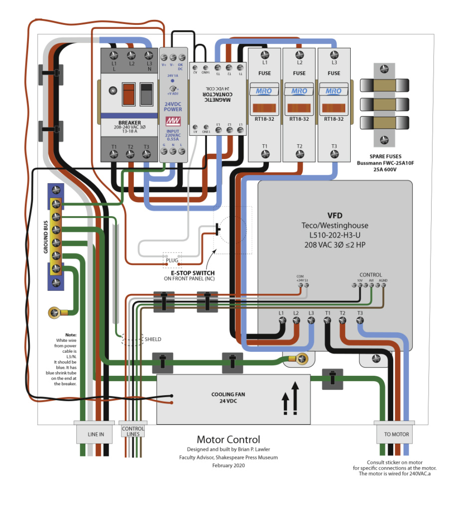
But it’s not that simple! In order to run a VFD, I would need an electromagnetic contactor, a circuit breaker, three fuses, a 24 volt DC power supply (to operate the contactor), and a cooling fan to keep it all from overheating. All of this went into a large steel utility box. And, into that box I had to drill and saw about 50 holes. I also designed and built a handsome remote control box. That box is now mounted close to the operator’s seat while the rest of this equipment is 18 inches away, on the top of the machine.

Since this is a State of California installation, and strict safety rules apply to all such things, the whole system was built to-code (which would be smart in any case). All the wires had to be of the correct gauge and color, and all of the connectors had to be properly prepared. The external wiring was run in oil-tight conduit.
In the process of building this device, I learned about DIN 35 standards and DIN 35 rails. DIN is the Deutsches Institut für Normung (German Institute for Standardization). These are systems devised for industrial electrical equipment, and they are impressive. If you need a flux capacitor, you can find one on eBay with the standard DIN 35 rail to mount it to your assembly. I bought several sections of DIN 35 rail, and put one strip in the back of my box. All of the other components simply clip onto to the rail, making assembly and wiring very easy. The whole thing has a clean, professional look as a result.
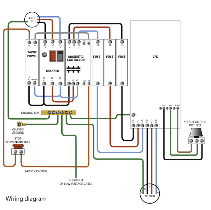
On projects like this I like to start with a schematic diagram to get the wiring figured out, then I advance to a scale drawing, with wiring, to-size. I do these drawings in Adobe Illustrator, and I am compulsive about them. The components must be accurately drawn, and the wires must be run correctly in the drawings. This allows me to see if things won’t fit, or if I am making a colossal error in putting the breaker to the right of the power supply. In one instance, I realized the the electromagnetic contactor should be mounted upside down. This allowed me to wire it more logically, and for the wires to move left-to-right, and never over or under the electrical components.
In this way I build my electrical projects more effectively by carefully following the drawing. If every wire is in the drawing, and I follow the drawing carefully, there is little chance of an error. With 208 volt power, errors have consequences I cannot afford.
Two steps in the construction of this electrical system were out of my normal routine. I seldom work on steel in my shop; usually I work on aluminum and wood. This one required a steel utility box with lots of holes. I drilled some, I cut one with a saber-saw, and I used chassis punches to cut three others. The chassis punches are the cleanest and easiest, as they cut a sharp edge with precision, and there are no metal chips that get loose.
The wire that comes out the front of the box is the wiring to the emergency-stop button on the box cover. I made a programming shunt to put on that cable when the front cover is removed for servicing.
To get all the holes in correct position, I made templates, cut on my CNC router, in an aluminum material called Alupanel. This stuff is a laminate of polyethylene with two outer layers of aluminum. It cuts easily on the router. Once those were made, I clamped them to the electric box’s sides, and then drilled or punched the holes through the holes in the template to match. On the top of the box are a pattern of 1/2 inch holes to vent heat. I drilled those on my drill press (not much fun).
Once the holes were drilled, I cut the burrs off, sanded the outer surfaces, and painted the box with a medium gray spray paint. This covered all exposed steel edges and made the box look more professional.
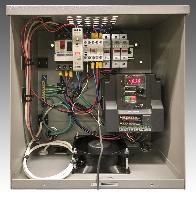
From there it was simply a matter of mounting all the hardware, and wiring the devices together. That took me about a day in the shop. I was careful to crimp, then solder, then shrink-tube most of the connectors. Adding lugs to the ends of wires proved unworkable in some cases; others worked fine. In the end, my finished motor control box looks a lot like the Adobe Illustrator drawing. Every wire is in its place; every tie-down is in proper position to keep the wires from getting confused.
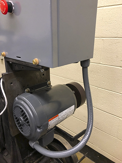
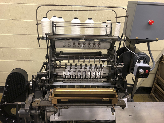
At the museum, I attached the control box to the top of the machine, I then installed the conduits for the motor and the power cord, and I wired the remote control box, and mounted it to the front of the machine on a steel bar that was already there. For this I drilled and tapped two holes for machine screws to hold the box in place. The control wiring is all low voltage, either 10 or 24 VDC, neither of which require conduit, so I ran the shielded control wire out of water-tight grommets on the back of the control panel, and into the control box. It looks great; it works great.
Meanwhile, in bed at night, I read the instructions for programming the Variable-Frequency Drive. Since it’s a solid-state device, and it has a programmable logic circuit within, there are many adjustments you can make in software. One can control minimum and maximum frequencies (translate to motor speed), speed ratios, and you can turn on the remote control wiring if you have it. That moves the power switch and motor speed controls to my external box. Inside that box are a simple power switch and a potentiometer. The potentiometer varies a 10 VDC signal from the VFD, causing it to speed up or slow down in proportion to the resistance of the potentiometer.
I couldn’t test these settings in my shop because I didn’t have 208 three-phase power to work with, and the motor was already mounted on the machine in the museum, so I postponed programming the VFD until the device was wired and ready to run on the Smyth machine. Once I moved the box to the museum and installed it atop the machine, I was able to apply power to the VFD and test it (the motor turned!). I was successful with the wiring of the control box and motor.
The fast-blow fuses and fuse boxes were purchased on eBay, and shipped from China at the same time as the Corona Virus outbreak. I was told by e-mail that these parts would be delayed. So I built the rest of the system without these optional but important parts. For testing, I still had the circuit breaker in the box. I left space for the fuse boxes once they arrived, and wired them in once they arrived. The DIN 35 parts are like building blocks; I mounted the wires, installed the fuses, then clipped the boxes onto the rail.
Mechanical problems were my next challenge. The original motor was about 50 percent larger than the new motor, and the mounting holes were further apart. At the beginning of the project I took the large cast iron frame to my shop and drilled and tapped four new mounting holes for the replacement motor. That left the new motor about one inch lower than the original. After installing the electric box and all of its connections, I put the drive belt back on, and it was too loose by about one inch (surprise!). The motor mount can be moved, but not enough to make up for the slack created by moving the motor down as I did. I had several possible solutions: 1 – move the motor up (couldn’t do this because the old holes were in the way), 2 – modify the mount plate (couldn’t do this because of the details in the iron casting), or 3 – get a shorter drive belt. This proved to be the best option because they are relatively easy to get, and the 1935 drive belt is well-worn. I ordered a two-inch (circumference) smaller drive belt from McMaster-Carr, the industrial hardware company in Los Angeles.
Another mechanical problem was that the new motor has a larger drive shaft than the old one did. I took the 5.5 inch phenolic pulley off the old motor and took it to a local machine shop to have it machined to the larger diameter, and keyed for the new shaft. This took a few days, but was expertly done. I installed the modified pulley on the new motor and it fits with precision.
Now all that is left is to install that belt and test the machine. I’m sure I’m not finished yet, as I have not cycled the machine under power yet. Once the new motor and all of its fittings are in place I will do that. I hope that there are no more problems, but I will not be surprised if there are. It is, after all, a machine that once worked in production, was then put out to pasture for several decades, then revived.
Addendum, March 9, 2025: I posted a new item about the Smyth machine that has relevance to this story. Though I did an exemplary job of building, designing and wiring the new motor and controls on the machine, I made a colossal error: I wired the motor to turn in the wrong direction (and it took several years to figure out the problem). Click on this link to read about that discovery, and the final steps in getting the machine to sew finished book blocks. It really works now!
Addendum November 1, 2025: I have scanned and published a PDF of the original 1935 Smyth Model 12 Instruction and Parts Manual. You can download that here.