

As a part of my Bishop Peak Portrait Project, I have built a couple of “printed” circuit boards. I made these on my CNC router, which I used to cut away the copper on a blank circuit board, leaving behind the traces for the circuit connections. On that circuit board is a Raspberry Pi computer which is programmed to control the camera.
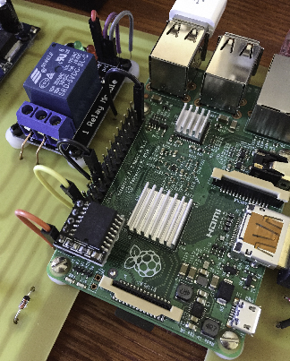
The real-time clock is mounted on the lower-left of the Raspberry Pi on the GPIO pins. Though it does not use them all, it’s connected to: 3.3V, 2 SDA, 3 SCL, 4 and GND.
On that Raspberry Pi computer I have mounted a real-time clock, also called a hardware clock. This is critically important to my project because the Raspberry Pi needs to know exactly what time it is.
Normal Raspberry Pi projects are desktop projects or robot projects, and most involve being connected to the Internet, either with a cable or with WiFi (requiring a WiFi module plugged into the USB plug on the edge of the Pi). The Linux operating system on the Raspberry knows where to get the time from the Internet, and it does it easily. But, disconnect the Internet, and the Raspberry reverts to the Beginning Of Time (which is December 31, 1999 at 4:00 p.m.).
I know that some scholars may argue that the Beginning Of Time happened much earlier, but the Linux Operating System knows!
I studied the world of keeping time on a Raspberry Pi, and I learned that I needed a Real Time Clock (RTC). Fortunately, these are available on every digital street corner, so I ordered one from Amazon, and it arrived just a day or two later. It was extremely easy to install, but a bit complicated to configure the software. I asked my friend Eric Johnson to help with that because he’s a Linux expert and he understands the methods for getting the operating system to see the clock and learn the time. This involves “blacklisting” the network time component of the operating system and telling it instead to look to the hardware clock that is installed. You must be connected to the Internet to make the changes, because in one Linux command you request the Internet time, then you write that time to the hardware clock. From that moment on, the clock knows what time it is.
The real-time clock I bought features a DS3231 chip, a device that appears to be the universal clock chip for these special devices. Most of our computers have a clock inside, one that is typically powered by a lithium-ion battery. That clock keeps track of the time and date when the power is turned off. When we restart, the clock tells the computer what time it is.
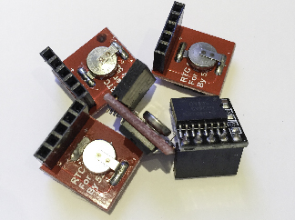
This is my ample collection of real-time clocks. The red ones, though purchased from a variety of suppliers, are all the same: they all use a super-capacitor to power the 3231 chip on board. The black one is a battery-powered circuit that uses a Lihium-Ion button battery for power.
The real-time clock I found features a “super capacitor” to power the small circuit board when the power is off. The seller on Amazon touted the “super capacitor” as being better than a battery because it would last longer. The buyer feedback told a different story. The clock received a range of ratings from no stars to 2.5 stars. Several people said that the super capacitor would only last a few hours at best.
I bought it anyway, mostly because it was easy, and it appeared that it would work in my circumstances. Two to three hours of life after a power failure was OK, because my system is powered by solar panels and a motorcycle battery. I couldn’t imagine my system failing for more than a minute or two.
After we installed the clock on my Raspberry Pi, I put the camera and controller on the roof of the library at Cal Poly, and it started working. At the start I had 9 ampere-hours of battery power in the box, which I calculated would last four days with no sunlight hitting the solar panels. In San Luis Obispo four days of cloud or rain is unthinkably rare, so I assumed that that would never happen. It happened in the first five days the camera was running. The computer ran out of power and the whole thing stopped.
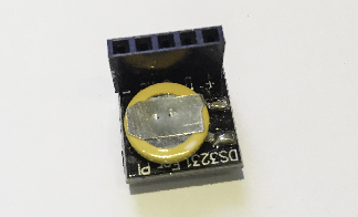
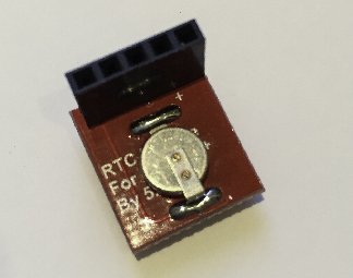
This is the power side of the two different real-time clocks. The upper circuit uses a Lithium-Ion button battery, the lower photo shows the super-capacitor on the bottom of the board. You can also see the five-pin connector that connects to the GPIO pins on the Raspberry Pi.
It started the next day when the sun came out, but in the break, the super capacitor had drained away, and the clock lost track of time. My system still worked, but it was 1999, and it was running on a schedule that was far from correct – shooting photos in the middle of the night, and it stopped shooting in mid-afternoon instead of 9:00 p.m. when it’s supposed to stop. I bought and installed a second battery, bringing the total available current to 19 ampere-hours, which gives the system 9 days of power with no solar recharging.
Though the camera was running well, I suspected that the real-time clock was defective so I replaced it with another of the same design. On close inspection I discovered that the super capacitor was soldered to the board, but that solder connection was “cold.” The contact was no good; an ohmmeter confirmed this diagnosis. I marked it as a bad component.
In the period between installing the original camera and circuit board I built the “printed” circuit board as a back-up. The first version was hand-wired, and it worked fine, but I needed a back-up. I tested the real-time clock that I bought, leaving it unpowered for periods of time ranging from a few minutes to a few hours. I learned that it would run out of power after just a few hours, and that was not acceptable.
I decided to order a battery-powered real-time clock. This one was also found on Amazon, but I really had to dig to get one with the battery. And, once ordered, Amazon indicated that its delivery would be several weeks later; it was coming from China, and not by air mail.
When the clock circuit arrived, I switched it for the one on my back-up circuit. It works fine, and I have tested it for periods up to one full day with no power. It comes right back up with the correct time. Since my two circuit boards are exactly the same size, I can substitute the one in the box now with the one on my desk, and get the battery-powered real-time clock into the working unit. Though it probably doesn’t make much difference, it will be nice to have a more reliable clock in the working camera box.
You can read the next installment here: The Bishop Peak Portrait Project ecosystem.