
This is part two of a blog about making a weather-proof time-lapse camera box, and the camera equipment to go inside it. You can read part one here.
With may plan to do a year-long time-lapse project, I began in earnest to finish the weather-proof box for the camera and electronics.
I decided to make the entire box with parts cut on the CNC router in my shop. I would make the box out of 3/4 inch Baltic plywood, which itself is weather-proof. When finished, I would spray a coat of clear acrylic over the box to add to its resistance to the weather.
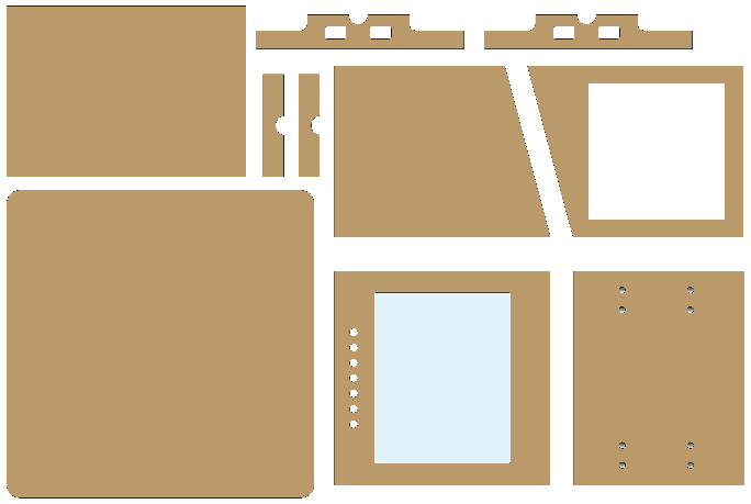
This is my box parts layout in Illustrator. The parts were cut from a sheet of Baltic plywood 29 x 44 inches in size. At the top are the two pieces that form the mounting bracket on the back of the box. This is a pretty simple pattern, and it was all cut with one router cutter – the 1/4 inch end cutter.
I designed the box in Adobe Illustrator, then converted the illustrations into a cutting plan in one big sheet. I have made enough parts on the CNC machine now that I don’t get too obsessive about drawing 3D versions to check them. I just forge ahead, cutting with abandon, and then I build. This has gotten me into trouble a few times, but in general I have great confidence in the process.
My work flow is to start the machine, and run the Mach3 cutting program to get set-up. Mach3 is the controller software for the CNC machine. It converts machine instructions from the design software into the actual motor pulses that move the stepper motors on the machine to their cutting positions. This software runs on a Sony Vaio laptop computer conneced to the CNC router by an Ethernet cable. I bring the cutting head close to the operator’s position, put a laser pointer tool into the router spindle, and locate the lower-left corner of the material I am cutting. This establishes the X,Y zero point. I then run the laser along the lower X-axis of the material to ensure that it’s set straight in the machine. I lock the material down using a variety of tools, one of which I described in a previous blog – the printer’s quoin.
To set the Z axis on the machine, I substitute a router cutter for the laser and use an automated zero-finding tool we have for the machine. This is a touch plate that uses electrical conductivity to establish when the cutter touches a brass plate in the tool. I connect an alligator clip to the cutter and run a routine that slowly lowers the cutter until it touches, and then – in an instant – the Z is set.
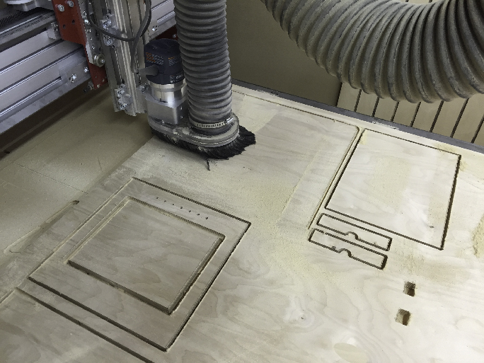
This is my CNC router making its way around the Baltic plywood and cutting the parts for my weather-proof camera box. The blue-silver device in the middle is the Bosch router on the machine. The gray hose is the dust-evacuation pipe that removes sawdust from the machine as it cuts. The machine makes a lot of noise, but it cuts with tremendous precision and makes construction of projects like this very simple.
Then, using a program called V-Carve on the same Sony computer I enter the dimensions of my material – width, height and thickness. V-Carve has the ability to import Illustrator vectors and convert them into cutting instructions. It’s a very nice program, and I am impressed by its features. Many people design in V-Carve, but I can’t run it on a Mac, so I use it only to convert my Illustrator files to cutting instructions, and then export those to the Mach3 cutting program in the language it understands – G-code. G-code is a fairly simple X-Y-Z coordinate language that is used on most machine tools. It gives simple instructions to a program in X-Y coordinates, it indicates the depth of the cut, and the speed of travel and the speed of the Z axis head. If you look at G-code, it’s easy to understand. Here is an example from this project:
G90
G0 X0.0000 Y0.0000 Z0.8000
(Cut outlines)
T1
(End Mill {0.25 inch} .25 inch pass depth 25percent stepover)
F50.0
F10.0
S8000
G0 X2.2756 Y3.1052 Z0.2000
G0   Z0.0500
G1   Z-0.2530 F10.0
G1 X8.2609   F50.0
G1 X9.0109
G3 X14.9606 Y3.2302 R0.1250
In those instructions, the positions are set, the tool is set, X-Y feed is set, Z feed is set, and the speed of the cutter is set (8000 rpm). Then there is a list of instructions that take the machine from one point to the next. In this case, the file has 2200 lines of instructions.
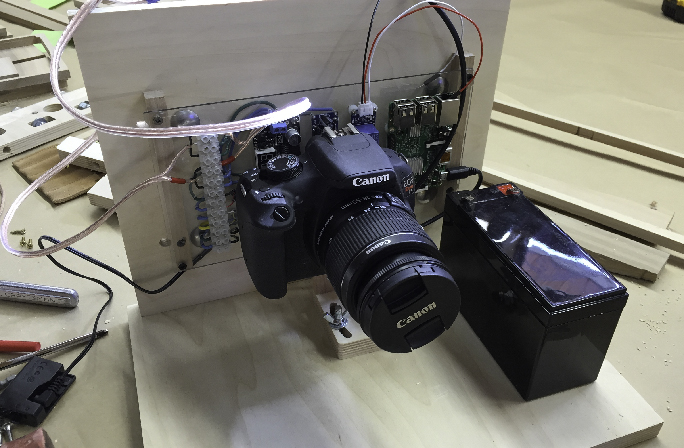
This shows the camera, the battery and all the electronics mounted in the partially finished box. I was testing the positions of the components to be sure that they would fit in the end.
In V-Carve, I choose the tool (a 1/4 inch router cutter is common), and then assign that cutter to a path as either a profile cut (outside) or an pocket cut (inside). V-Carve also has special controls for drilling, and for cutting lettering (which it does beautifully). Our CNC machine doesn’t change cutters automatically, so I am usually thoughtful about grouping my cuts to use the same cutter as much as possible, then I change the cutter and move to other cuts that use that one. I always save the outside profile for last, which helps me to avoid the cut piece breaking free of its surrounding material.
This weather-proof box included both inside and outside cuts, all of which were very simple. I transferred the file to V-Carve and prepared to cut all the needed pieces out of one half-sheet of Baltic plywood. It took about 30 minutes total, and when I was finished, I had all of the parts (except the door, which I cut later to fit). Building the box was then just a matter of assembling the pieces and screwing it together with stainless steel screws.
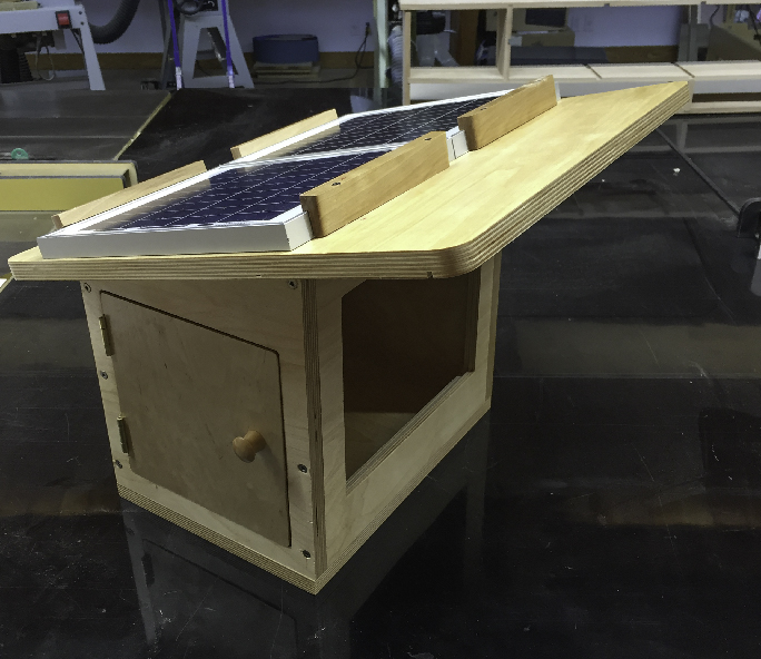
The nearly-finished camera box sports two solar panels on its roof, a hinged access door, and the opening in the front for the glass (yet to be installed in this photo). There is a tiny notch in the underside of the roof board whose job is to cause water to drip off the roof there, and not travel down to the glass.
The camera box will be mounted on a steel pole made of electrical conduit. I measured that conduit, then designed a clamp mechanism made-up of two pieces of Baltic ply that will pinch the conduit and hold the camera box in-place. I plan to add two additional posts in the front of the camera box to stiffen its resistance to the wind.
You can see in these illustrations and photos how the box went together. It’s finished now and ready to house the camera and electronics to do its year-long time-lapse job.
In my next blog I build a new circuit board, and include images of the mounting and assembly of the camera on the roof of the building at Cal Poly. Read that blog here.