
What’s been going on since December?
I’ve been spending a lot of time making a cabinet for my camper (another thing I designed in Illustrator and built on my CNC Router). That has taken a tremendous amount of time, and it has shown me over and over again that the CNC is a great addition to a workshop, but not a substitute for more traditional tools and common sense. I also re-learned the old axiom about measuring twice and cutting once, as I had to modify the cabinet after it was built to accommodate some hardware in the back of my van that I had failed to see when I made the first measurements. More on that in another blog that I will write when I get the time.
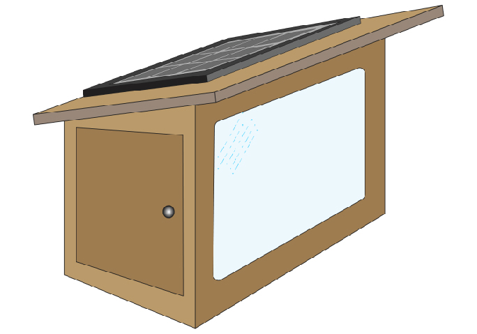
This is an illustration of my time-lapse camera box. It must be weather-proof so that it can survive on a hot roof for over a year.
Speaking of time, my major project since December is a super-duper water-resistant time-lapse camera box and system that I am installing on the roof of the Kennedy Library at Cal Poly, my place of work. My plan is to take a “portrait” of a local mountain every five minutes for a full year and put the photos from that camera into a montage in one of our buildings.
The camera idea came to me last year after I finished the Mars photo project of which I wrote in this blog in September.
I have done a similar project with a similar box years ago when I photographed the construction of a home over a four-year period. The box proved to be very successful, so I cloned it to make a more modern version, this one a little smaller, but a little more robust. As I write this, I am listening to the sounds of strong winds buffeting my home – I need to be sure that the camera and its mounting can withstand that kind of assault in addition to any rain that might fall in the coming year. We get so little rain that it’s almost silly designing for it, but I must protect the equipment and I must hope for rain!
I over-engineer those projects for a couple of reasons. One is that I need to be sure that this camera does not move at all over the one year and 11 days in which I will be making my study. The second reason is that I enjoy the challenge of making things. I also decided to make my own time-lapse computer this time using a Raspberry Pi microcomputer and other components on a circuit board of my own design. I liked the idea of learning how to program the Raspberry Pi, and learning about these popular devices. My circuit is bigger and it consumes more power than is necessary for such a small task, but I decided to do it myself (as much as I could) and get the project running, and I gave up efficiency for the ability to learn how to do it myself.
I began with the Raspberry Pi and a Canon T5 camera that I purchased for the project. The camera uses battery power that under the best of circumstances would allow it to run for a day or so. I solved that basic problem by purchasing a power supply adapter for the T5 from a Chinese maker of camera accessories. This adapter came with a 110V transformer power supply which I cut off and put into e-waste. I only wanted the plastic battery “cheater” and cable. The Canon runs on 7.2 volts, which required me to come up with that power on my circuit board.
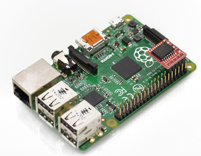
My Raspberry Pi computer with its on-board real-time clock (red circuit, upper-right). This combination provides a complete Linux computer with a precise clock to keep track of my photo schedule.
My camera box must be a stand-alone device, not relying on electrical power from the building on which it will sit. I designed it to have two 5-watt solar panels on the top to keep a motorcycle battery fully charged for the year it will be in service. Those solar panels go through a solar charge controller that monitors the battery and keeps it topped-off when the sun is shining. Motorcycle batteries provide 12 volts of power, so I bought a small DC-to-DC power supply to change the voltage from 12 to 7.2 volts to run the camera. Check.
The Raspberry Pi is a complete computer on a board the size of a business card. It’s a very popular computer for making projects – robots, sensors, control circuits, and more. The Raspi (as its adherents call it) runs a free version of Linux and it comes with a development environment for writing programs in Python. I have done a lot of small-scale programming in other languages including C and AppleScript, but this was my first excursion into Python (and I didn’t go far, as my program is so simple).
Power for the Raspi is 5 volts, so I bought another DC-to-DC power supply to deliver that power to the computer. From the Raspi I take a 5 volt line to a small relay, and from there I trigger the camera with the computer.
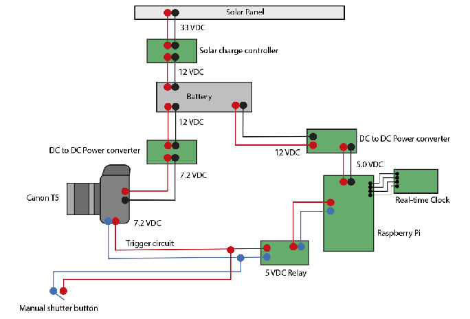
This is my block diagram of the time-lapse circuit for my project. It’s a relatively simple plan, made into reality with components and modules I purchased at Amazon.com.
When I had the whole circuit designed, I converted the block diagram in Illustrator to a cutting plan for the actual circuit board. I measured each of my components (Raspi, two power supplies, relay, push-button, terminal strip) and designed their precise locations on the board. From there I made a pattern for the CNC Router, and I cut the board and drilled all the necessary holes into a sheet of polycarbonate plastic.
Circuit designers use a technique called breadboarding when making hardware. I bought a breadboard to go with my Raspi and I began the process of making my circuit work. I wired power to the power supply that drives the camera. When tested, it worked perfectly. Check.
Then I moved to the Raspi and the relay. I wired the relay to trigger the camera’s remote input (a simple open circuit, which when closed causes the camera to take a photo). I wired a push-button to the board so that I can trigger the camera manually. That push-button worked perfectly, and the relay, when triggered by a AA battery, worked perfectly. Check.
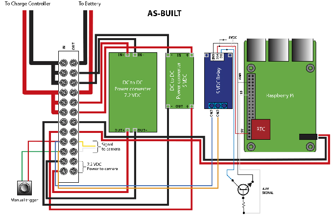
…and this is the nearly exact diagram of the components and their positions for the circuit board. I used this illustration to make the CNC cutting file that I used to drill the holes for all the components in a sheet of polycarbnate plastic to make the circuit board.
I bought a book about programming the Raspberry Pi, and I went through the book, following the assignments and progressing as a new Python programmer, but I was impatient. I only need to push an output pin “high” to create a signal to the relay for a moment. I studied the book’s example for making an LED flash. That was exactly what I needed. I built a circuit using the Raspi and an LED. I wrote the program and tested it, and voila! – the LED flashed. Check.
Then I took the LED out of the circuit and connected the signal from the Raspi to the signal side of my relay and I ran my program. It failed to work. Uncheck.
I studied various fora on controlling relays with the Raspberry Pi, learning that the small computer does not provide enough current to drive a relay. What I needed was a relay with a lower power threshold on its signal side. I ordered two on Amazon Prime!). While those were in the mail I thought that I could solve the problem with a transistor, making what is essentially an electronic switch. I read-up on transistor circuits, and learned that an NPN transistor can rather easily be wired to control the signal side of my relay. Armed with this information, I studied very simple transistor circuits that I found online, and discovered that I could make a simple electronic switch with a transistor, a resistor and a diode. I got my friend D.K. Philbin involved because he has years of experience with electronics. I gave him the challenge, and he calculated the values of the resistor and diode, and he sent me a little envelope with an NPN transistor, the resistor and the diode. I built the circuit and had it working in less than an hour!
Check!
The Raspberry Pi hummed along, sending its pin 18 “high” to drive my transistor every five minutes, and the transistor sent 5 volts of power to the signal side of the relay, and the relay closed the circuit on the Canon camera, causing it to take a photo. This was going very well! My circuit was complete!
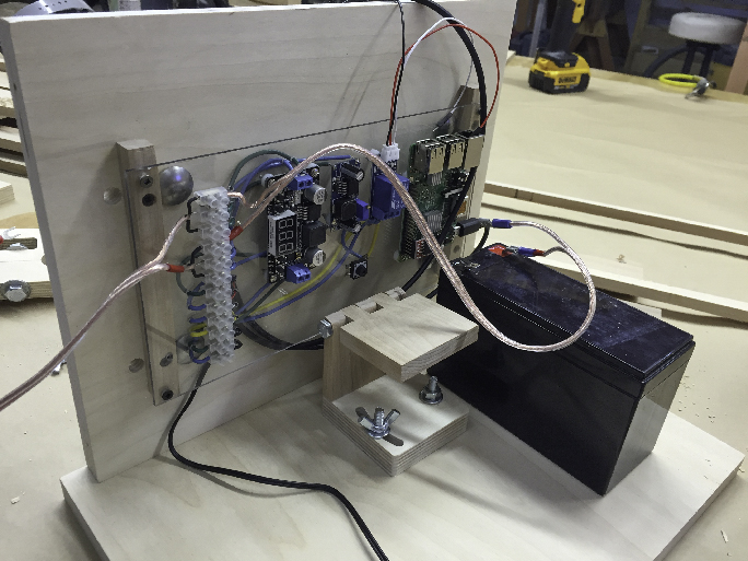
This is the nearly complete circuit board mounted in the back of the weatherproof box for a test fit. The motorcycle battery is on the right. My wooden camera mount is in the center, still in need of a couple of parts. The solar charge controller is mounted in the ceiling of the box, which is not shown in this photo.
I need the entire system to work without failure for a year without outside power, and I was relying on 10 watts of solar power as my power source. I wired an ammeter into the circuit between the battery and the board and I powered it up. With all of the components going, it consumes .23 amps of power (a lot for a small device like this). At that rate, I would run my battery down in less than three days and the whole contraption would come to a screeching halt. I obviously needed more power. In order to run rain or shine, I wanted to have three to four times that much energy. I bought another solar panel and added 30 more watts to the system. After installing that panel I tested the solar system, finding that I am generating .73 amps in bright sunlight and keeping the battery at full-charge. Check!
The Linux side of my program was done my by dear friend Eric Johnson who dreams in Terminal code. He came over on Saturday and installed a couple of modules of code to the kernel on the Raspberry Pi. That little computer uses the Internet to get the time. My system will not be connected to the Internet, so I purchased a module called a real-time clock to add time to the Raspi. Eric instructed the Raspi to get the time on startup, and then to use the time to trigger my very small program to take photos in a schedule he devised using a Linux command called “cron.” Cron is really cool because it can be instructed to do something (run my program) at intervals. Eric instructed it to start taking photos every five minutes beginning at 5:00 a.m. and continuing until 9:00 p.m. We tested it and it works. Check!
My time-lapse circuit is now complete and the camera is successfully taking photos every five minutes. On my desk.
Now for the enclosure – I went to work on the box (I was actually doing both at the same time in two locations). More on that in the next blog. You can read about the enclosure here.
That’s an interesting project. It is a simple idea. But, as with many things, the devil is in the details. Good for you and your friends for getting it all to work. I look forward to seeing the results one day.
My son-in-law introduced me to R-pi. I should go back and take a closer look at what it can do.
Hi Jim,
I agree that the devil is in the details. The circuit is sitting to my right on the desk, and it has stopped working. Hmmmmmmm.
The Raspberry Pi has infinite possibilities, and it’s surprisingly fast.
I use it with the HDMI output to a big display, and it’s really nice.
I plan to get to know it a lot better in the coming months.
Best wishes,
Brian P. Lawler